
Adapter for an anesthetic vaporizer

an anesthetic vaporizer and adapter technology, applied in the direction of respirator, liquid handling, packaging goods type, etc., can solve the problems of confusion in the marketplace and among anesthesiologists or technicians, volatile liquid anesthetics that can evaporate, and system failure to work properly

Inactive Publication Date: 2009-06-16
BAXTER INT INC +1
View PDF33 Cites 33 Cited by
  • Summary
  • Abstract
  • Description
  • Claims
  • Application Information

AI Technical Summary

Benefits of technology

This patent describes an adapter that can be used to transfer anesthetic agent from a container to a vaporizer. The adapter includes a spout with a movable valve and a stationary contact member. When the spout is inserted into the vaporizer, the contact member moves the movable valve and the adapter valve is opened by the stationary portion of the vaporizer. This design eliminates the need for competing springs and allows for the sequential opening of the vaporizer valve before the adapter valve. The technical effect of this invention is to provide a more efficient and reliable method for transferring anesthetic agent from a container to a vaporizer.

Problems solved by technology

Liquid anesthetics are relatively volatile and can evaporate at room temperature.
One potential drawback with the filling systems of Braatz et al. and Grabenkort et al. is that they rely on the proper selection and quality control of competing biasing springs of different strength in the adapter and vaporizer valving systems in order to cause the preferred sequential opening of the vaporizer before the adapter.
Of course, this system does not work properly if the springs, through lack of manufacturing quality control or for other reasons, are not of the proper strength.
While the above filling systems eliminate the need to properly select or calibrate the biasing springs, one drawback with them is that they require a different vaporizer valving system that may not be compatible with prior competing-spring systems and may result in confusion in the marketplace and among anesthesiologists or technicians.

Method used


Image

  • Adapter for an anesthetic vaporizer
  • Adapter for an anesthetic vaporizer
  • Adapter for an anesthetic vaporizer

Examples


Embodiment Construction

[0025]Although the present invention is described as illustrated in the attached drawings of the preferred embodiment, it is to be understood that the disclosed embodiments are merely exemplary of the invention, which may be embodied in various forms. Therefore, specific details disclosed herein are not to be interpreted as limiting, but as a representative basis for teaching one skilled in the art to variously employ the present invention in virtually any appropriate manner.

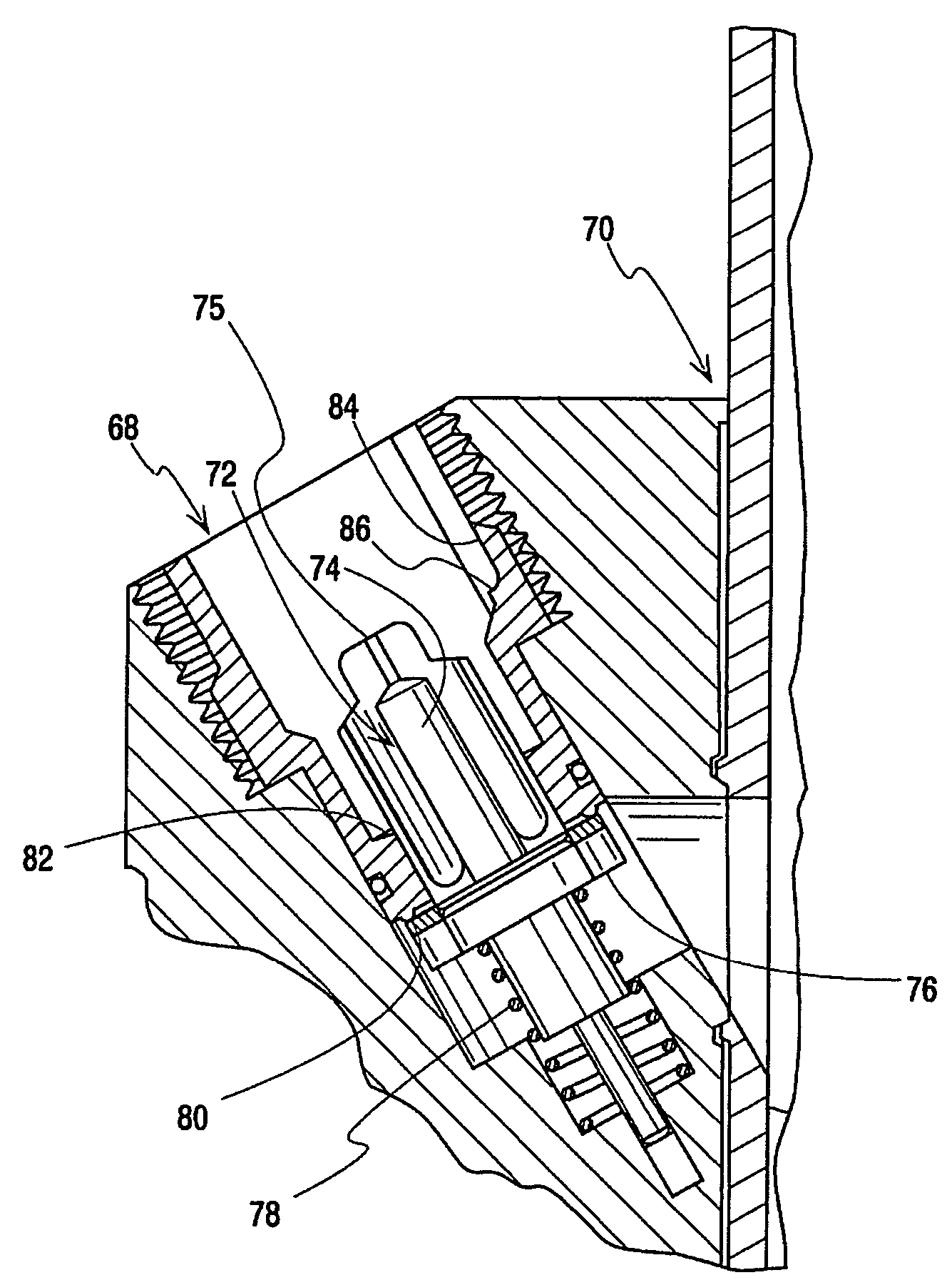
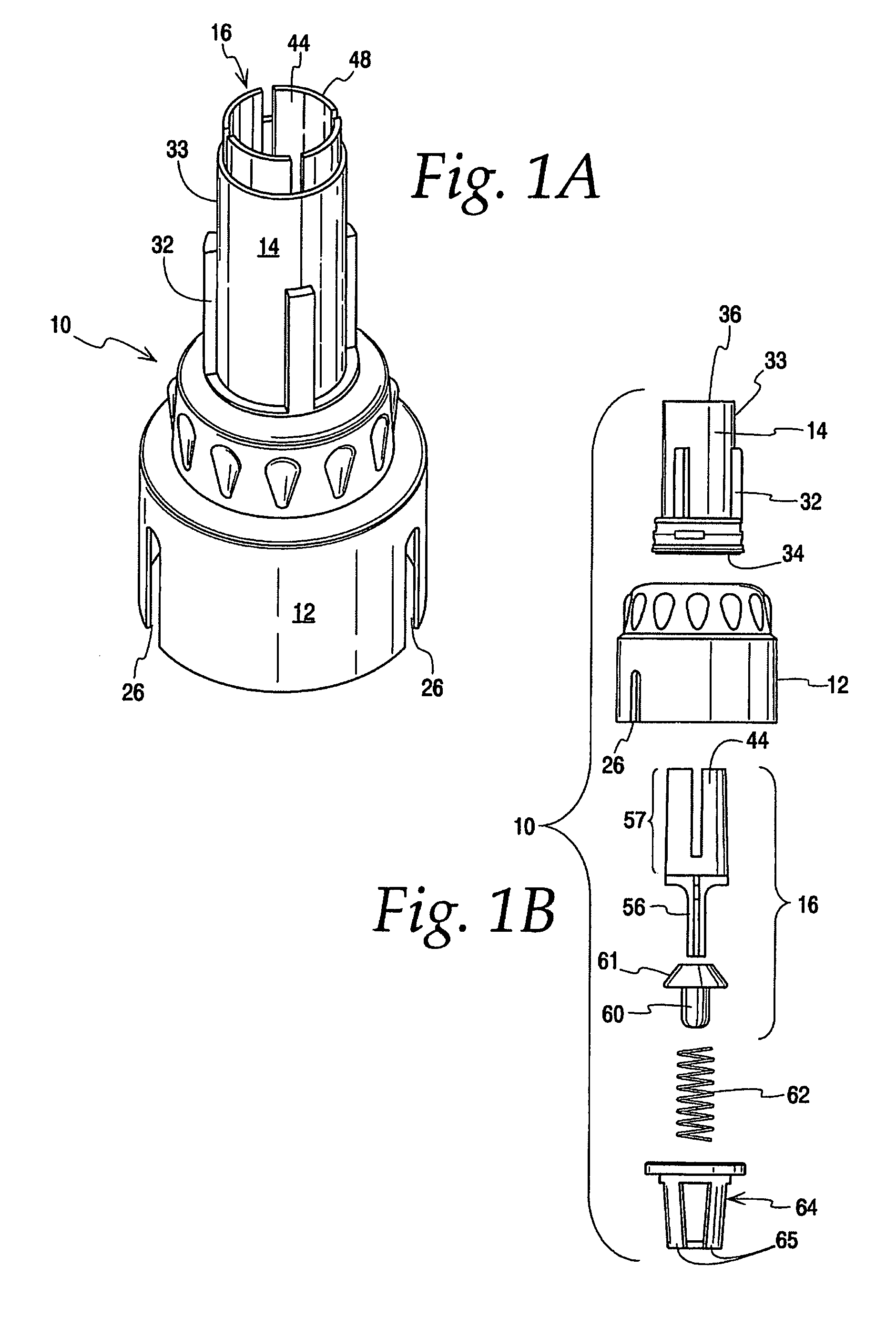
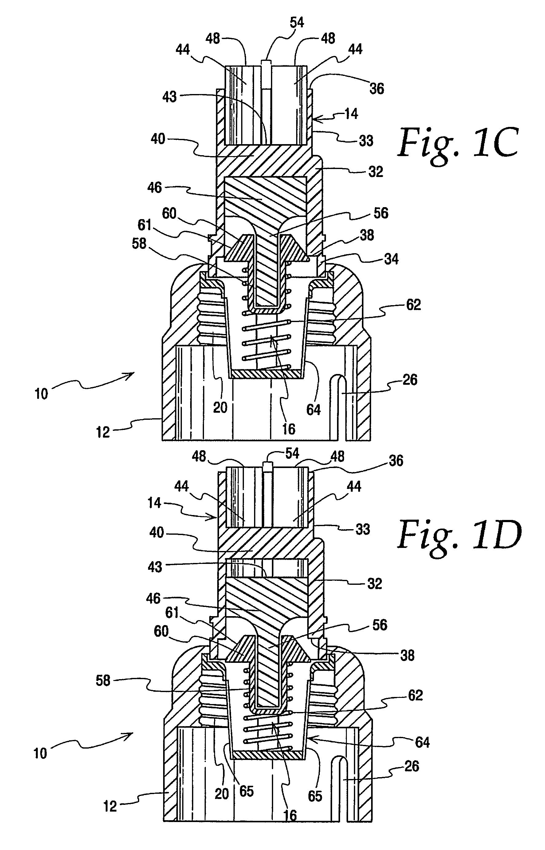
[0026]FIGS. 1A-1D show an adapter according to the present invention. The adapter is generally identified as element 10 in FIGS. 1A-1D. The illustrated adapter 10 includes a base 12, a spout 14, and a movable adapter valve assembly 16. Although illustrated as separate pieces, certain of these may be combined or molded in a single piece, if so desired. The base 12 is located at a lower end of the adapter 10 and is configured to be attached to a liquid anesthetic agent container or bottle 18, which is illustrated ...


PUM

PropertyMeasurementUnit
distanceaaaaaaaaaa
axial distanceaaaaaaaaaa
diameteraaaaaaaaaa

Abstract

An adapter is provided with a base mountable on a bottle containing a liquid anesthetic agent. A spout extending upwardly from the base is received by an inlet port of an anesthetic vaporizer having a movable valve assembly and a stationary portion, such as a radial ledge. The spout includes a stationary contact member configured to contact and open the vaporizer valve assembly when the spout is inserted into the inlet port. The adapter also includes a movable valve assembly that is contacted and opened by the stationary portion of the inlet port when the spout is inserted into the inlet port. The contact member and adapter valve assembly are arranged such that, when the spout is inserted into the inlet port, the contact member opens the vaporizer valve assembly before the stationary portion of the inlet port opens the adapter valve assembly.

Description

BACKGROUND OF THE INVENTION[0001]1. Field of the Invention[0002]This invention generally relates to apparatus for allowing selective fluid communication between an anesthetic agent container and an anesthetic vaporizer. More particularly, the invention relates to an adapter mountable on an anesthetic agent container for connecting the container to an inlet port of an anesthetic vaporizer.[0003]2. Description of Related Art[0004]During surgical procedures, it often is necessary to anesthetize a patient. One method of delivering anesthetic is in a gaseous form, which is inhaled by the patient. For the safety of the patient and medical personnel, the anesthetic agent is typically transported in liquid form in a suitable container. Known liquid anesthetics include halothane, isoflurane, and sevoflurane. The liquid anesthetic is ultimately dispensed into an anesthetic vaporizer, which mixes the liquid anesthetic agent with a carrier gas, such as oxygen or nitrous oxide, that is inhalable...

Claims


Application Information

Patent Timeline
Patent Type & Authority Patents(United States)
IPC IPC(8): B65B1/04
CPCA61M16/183A61M39/26F16L41/004A61M2205/6045
Inventor CHOTENOVSKY, DAVID J.
Owner BAXTER INT INC
Learn More