Inverse thermal acoustic imaging part inspection

a technology of inverse thermal acoustic imaging and part inspection, which is applied in the direction of optical radiation measurement, specific gravity measurement, instruments, etc., can solve the problem of difficult detection of parts flaws

Active Publication Date: 2009-06-23
RTX CORP
View PDF16 Cites 4 Cited by
  • Summary
  • Abstract
  • Description
  • Claims
  • Application Information

AI Technical Summary

Problems solved by technology

It is difficult to detect some part flaws such as small cracks.

Method used


Image

  • Inverse thermal acoustic imaging part inspection
  • Inverse thermal acoustic imaging part inspection
  • Inverse thermal acoustic imaging part inspection

Examples


Embodiment Construction

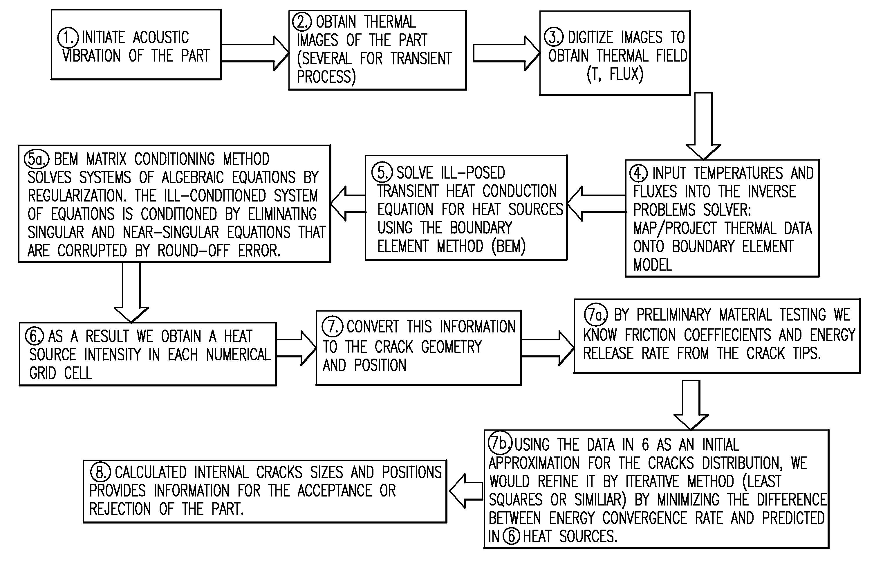
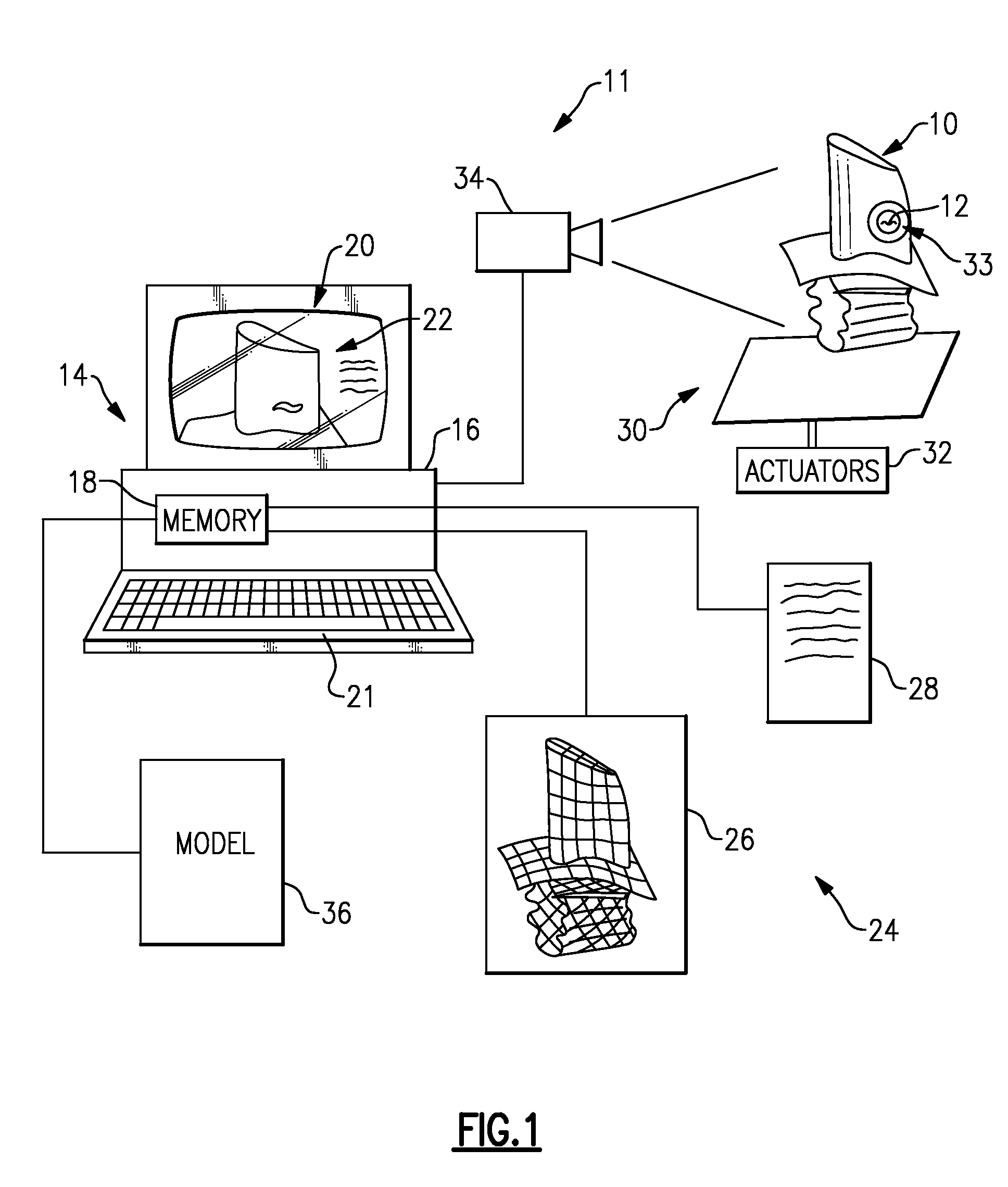
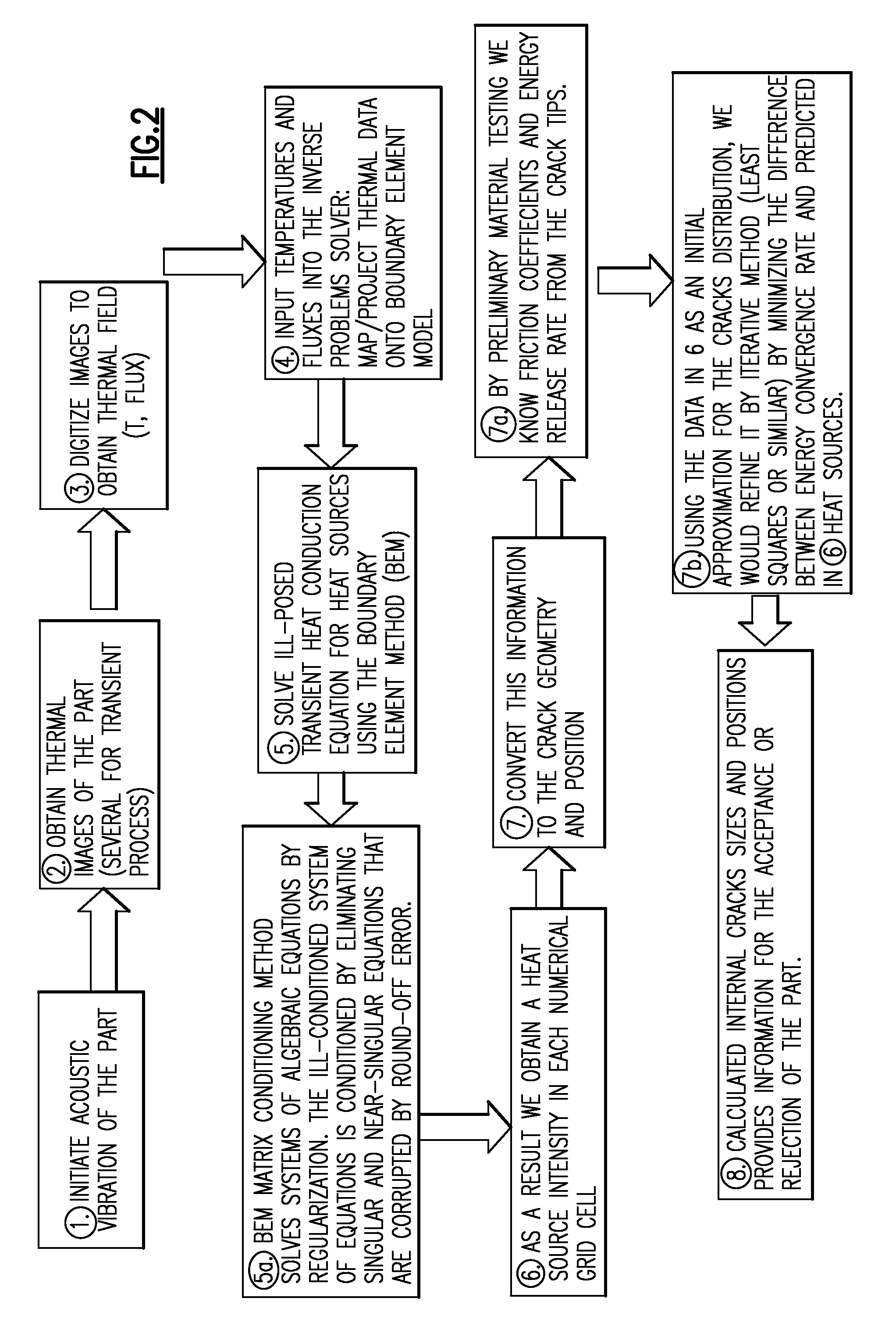
[0009]An inspection system 11 for identifying features within a part 10 such as a flaw is illustrated in FIG. 1. The inspection system 11 can be fully automated. The part 10 having a flaw 12 is mounted on a vibration device 30 that is excited using multiple actuators 32 of different frequency. The vibration device 30 may be a shaker table or ultrasonic devices capable of vibrating the part 10 in a range of, for example, 500 Hz-100 kHz.

[0010]Due to the vibration imparted on the part 10 by the vibration device 30, heat is generated at any flaws or cracks within the part 10 due to friction and plastic deformation during each loading cycle. This heating, which is illustrated schematically at 33, results in a temperature rise over the nominal structure temperature of the part 10. The temperature rise caused by a crack is distributed over a range wider than the strained distortion and, hence, can be detected using an infrared camera 34, for example. Images of the exterior of the part 10 a...


PUM

PropertyMeasurementUnit
thermal imageaaaaaaaaaa
heat transferaaaaaaaaaa
transient inverse heat conduction equationaaaaaaaaaa

Abstract

A method of identifying a flaw in a part is provided that includes vibrating a part to induce heat. The heat originates in any flaws in the part. A thermal image is obtained using, for example, an infrared camera. A mathematical representation of the thermophysics, such as the heat conduction or thermal energy equations using the boundary element method or finite element method is used to identify a source and an intensity of the heat identified with the thermal image. Using the source and intensity of the heat, flaw characteristics for the part can be determined. The method is employed using an inspection system that includes a vibration device for vibrating the part. An imaging device, such as an infrared camera, measures temperature on the surface of the part. An assumption is made or additional measurements are taken to obtain values for surface flux or surface heat transfer coefficients. A processor communicates with the imaging device for receiving the surface temperature. The processor includes computer memory having part characteristics and mathematical equations. The processor uses the measured surface temperature, assumed or measured heat flux or heat transfer coefficients, part characteristics and mathematical equations to determine the flaw characteristics in the part.

Description

BACKGROUND OF THE INVENTION[0001]This invention relates to a method and apparatus for inspecting a part to identify, for example, flaws within the part.[0002]Many component parts must be examined to insure that there are no part defects that would compromise their use. This is particularly true in the case of aircraft components such as turbine airfoils. The part must be examined in a non-destructive manner so that the part can still be used after examination. It is difficult to detect some part flaws such as small cracks. Further, any internal part defects may not become evident using traditional non-destructive inspection techniques such as ultrasound, x-ray, fluorescent penetrants or eddy current.[0003]What is needed is a non-destructive inspection method and apparatus that is capable of identifying part flaws such as cracks.SUMMARY OF THE INVENTION[0004]A method of identifying a flaw in a part is provided that includes vibrating a part to induce heat. The heat originates in any ...

Claims


Application Information

Patent Timeline
Patent Type & Authority Patents(United States)
IPC IPC(8): G01N29/04G01N25/72
CPCG01N25/72
Inventor STAROSELSKY, ALEXANDERMARTIN, THOMAS J.SIDWELL, CARROLL V.OUYANG, ZHONGSMITH, KEVIN D.
Owner RTX CORP
Why Eureka
Try Eureka