
Electronic apparatus and power supply controlling method

a technology of power supply and control method, which is applied in emergency power supply arrangements, television systems, instruments, etc., can solve the problems of not being able to operate, the consumption current supplied from the usb bus is greater or equal to 500 a, and the usb standard is not satisfied

Inactive Publication Date: 2009-06-23
SONY CORP
View PDF16 Cites 4 Cited by
  • Summary
  • Abstract
  • Description
  • Claims
  • Application Information

AI Technical Summary

Benefits of technology

[0008]The present invention has been made in view of the situation described above, and it aims at switching input power source efficiently in accordance with a load of a device.

Problems solved by technology

However, when a portable electronic device is connected to another electronic device via a USB cable, if the power source is simply switched to electric power supplied from the USB cable, operation is not allowed when a current exceeding 500 mA is needed.
Furthermore, in a portable electronic device, when a backup battery (e.g., a secondary battery or a capacitor) is charged during USB suspend, a consumption current supplied from the USB bus becomes greater than or equal to 500 μA, so that the USB standard is not satisfied.
That is, when the current exceeds the value defined by the USB standard, error could occur in signal processing or the like.

Method used


Image

  • Electronic apparatus and power supply controlling method
  • Electronic apparatus and power supply controlling method
  • Electronic apparatus and power supply controlling method

Examples


Embodiment Construction

[0022]Now, an embodiment of the present invention will be described with reference to the drawings.

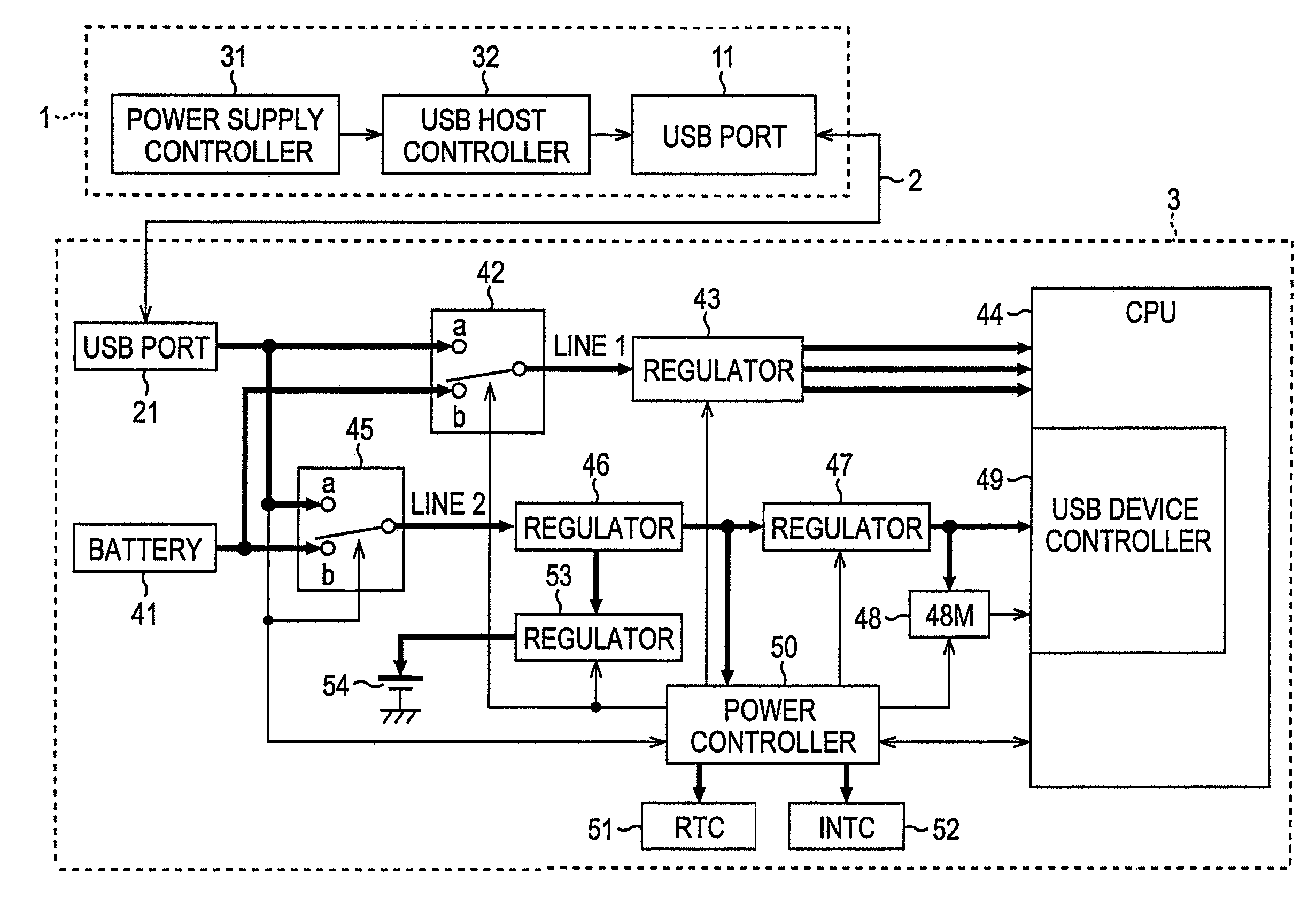
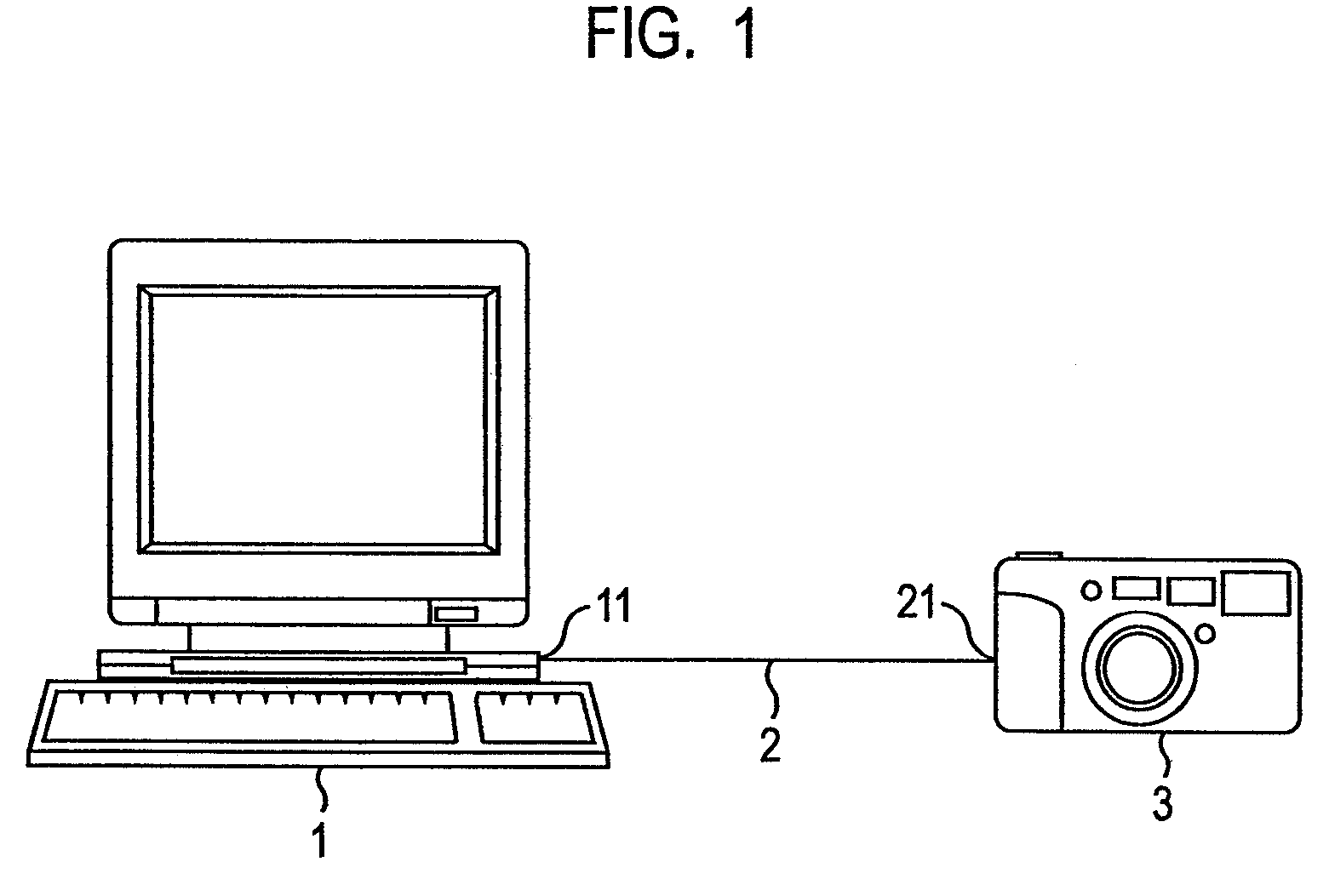
[0023]FIG. 1 is a diagram showing an example connection between a personal computer and a digital still camera according to the present invention. Referring to the figure, a USB port 11 of a personal computer 1 is connected to one end of a USB cable 2, and the other end of the USB cable 2 is connected to a USB port 21 of a digital still camera 3. Thus, the personal computer 1 and the digital still camera 3 are USB-connected to each other.

[0024]The personal computer 1 is either connected to a power source that is not shown and operates by a power supply voltage thereof, or operates by electric power of a battery that is not shown. Furthermore, the personal computer 1 supplies electric power to the digital still camera 3 through the USB cable 2.

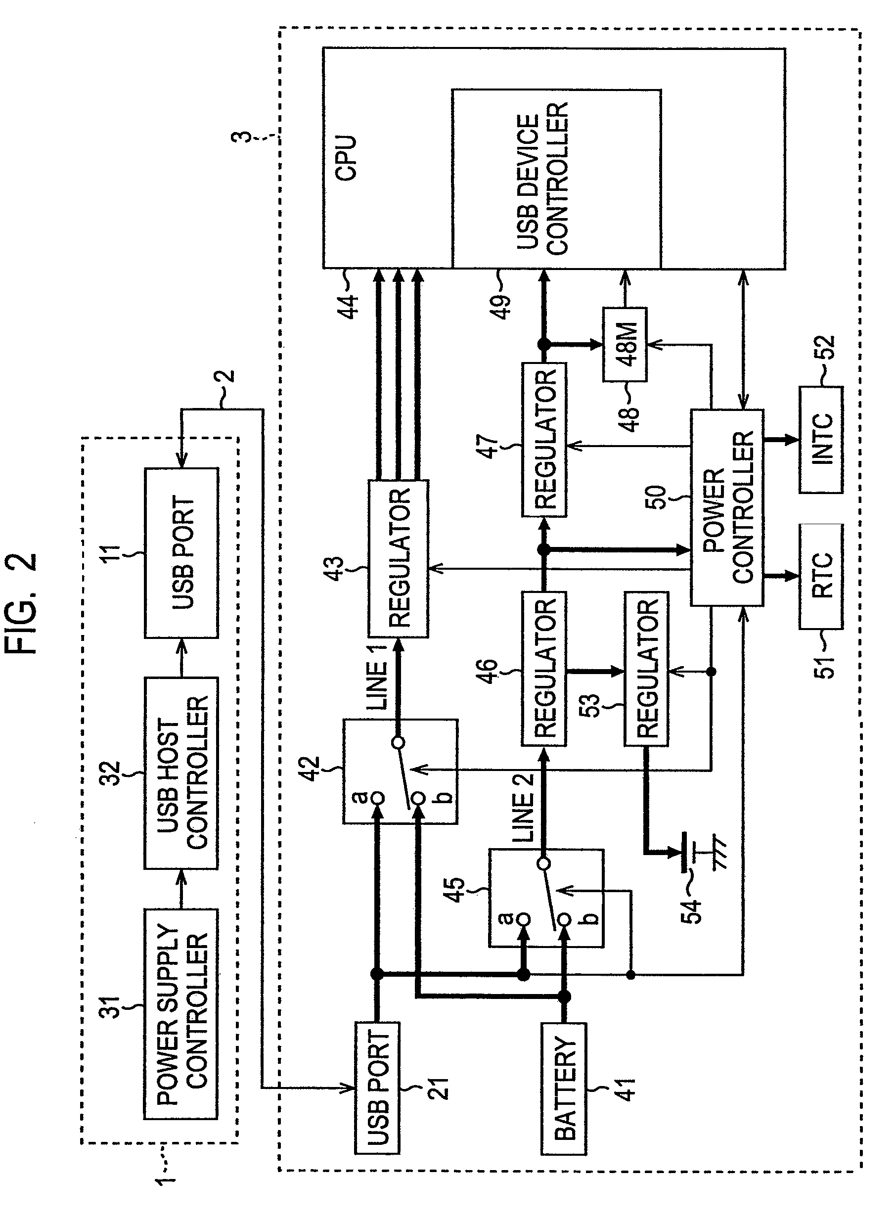
[0025]The digital still camera 3 operates by electric power of a battery 41 (FIG. 2), and also operates by electric power that is supplied from t...


PUM


Abstract

The present invention relates to an electronic apparatus and a power supply controlling method with which input power source is switched efficiently in accordance with a load of a device. A power controller 50, upon detecting a USB connection, monitors power consumption of a CPU 44 based on the operation status of the CPU 44, and controls a switch 42 in accordance with a current supplied from a USB cable 2. When the current is less than or equal to 500 mA, the switch 42 is switched to a terminal a. Before configuration, when the current is less than or equal to 100 mA, the switch 42 is switched to the terminal a, and then a regulator 43 is controlled so that the current will not exceed 100 mA. In USB suspend, the switch 42 is switched to a terminal b, and a regulator 53 stops output to a backup battery 54. The present invention can be applied to a digital still camera supporting USB.

Description

[0001]This is a Continuation Application of U.S. Ser. No. 10 / 508,629, filed Sep. 16, 2004, now abandoned which is a 371 Application of PCT / JP03 / 00645, filed Jan. 24, 2003, which claims the benefit of Japanese Application Japan P2002-077730, filed on Mar. 20, 2002, all of which are hereby incorporated by reference in their entirety herein.TECHNICAL FIELD[0002]The present invention relates to electronic apparatuses and power supply controlling methods. Particularly, the present invention relates to an electronic apparatus and a power supply controlling method with which input power source is switched in accordance with a load of a device when a portable electronic device such as a digital still camera is connected to another electronic device via an external interface.BACKGROUND ART[0003]Recently, battery-operated portable electronic devices having USB (Universal Serial Bus) interfaces, such as digital still cameras, are becoming common. Such devices can be connected to other electron...

Claims


Application Information

Patent Timeline
Patent Type & Authority Patents(United States)
IPC IPC(8): H02J9/04H01H35/00H01H45/14H01H67/00H02J1/10G06F1/26G06F1/28G06F1/32H04N5/232H04N101/00
CPCG06F1/266G06F1/28G06F1/3203
Inventor MASUI, ICHIROOGAWA, KATSUNORISAKAI, KENICHI
Owner SONY CORP
Learn More