Automatic decompression mechanism for an engine

a technology of automatic decompression and engine, which is applied in the direction of mechanical equipment, machines/engines, manufacturing tools, etc., can solve the problems of difficulty in reducing the cost and size of the mechanism

Inactive Publication Date: 2009-06-30
MTD PRODUCTS
View PDF21 Cites 4 Cited by
  • Summary
  • Abstract
  • Description
  • Claims
  • Application Information

AI Technical Summary

Benefits of technology

[0009]In operation, the biasing means is adapted to urge the centrifugal member into a decompression position when the cam gear is rotating at a lower speed, wherein under the action of a lower centrifugal force, the projecting portion of the centrifugal member is caused to project through the opening of the slot region and above the cam profile surface, thereby causing the projecting portion to temporarily actuate the cylinder valve mechanism, with results being that the starting force required to start the engine is reduced. Once the engine has been started and the cam gear is rotating at a higher operating speed, the centrifugal member pivots into a non-decompression position, wherein under the action of a higher centrifugal force, the projecting portion of the centrifugal member recedes back through the opening in the slot region and below the cam profile surface so as to prevent the projecting portion from actuating the valve mechanism during normal engine operation.
[0010]In an exemplary embodiment of the invention, the cam gear further includes a plurality of boss members which are configured in shape and size to be inserted into a set of mating apertures of the associated cover member. Such configuration allows the cover member to be fixedly attached to the cam gear, and allows the biasing means to pivotally retain the centrifugal member in the decompression position.

Problems solved by technology

One disadvantage of such prior art designs is that the assembled structures comprise a relatively large number parts, making the manufacture and assembly of the decompression mechanism relatively troublesome, and moreover making it difficult to reduce the cost and size of the mechanism.

Method used


Image

  • Automatic decompression mechanism for an engine
  • Automatic decompression mechanism for an engine
  • Automatic decompression mechanism for an engine

Examples


Embodiment Construction

[0021]The invention will now be described in the following detailed description with reference to the drawings, wherein preferred embodiments are described in detail to enable practice of the invention. Although the invention is described with reference to these specific preferred embodiments, it will be understood that the invention is not limited to these preferred embodiments. But to the contrary, the invention includes numerous alternatives, modifications and equivalents as will become apparent from consideration of the following detailed description.

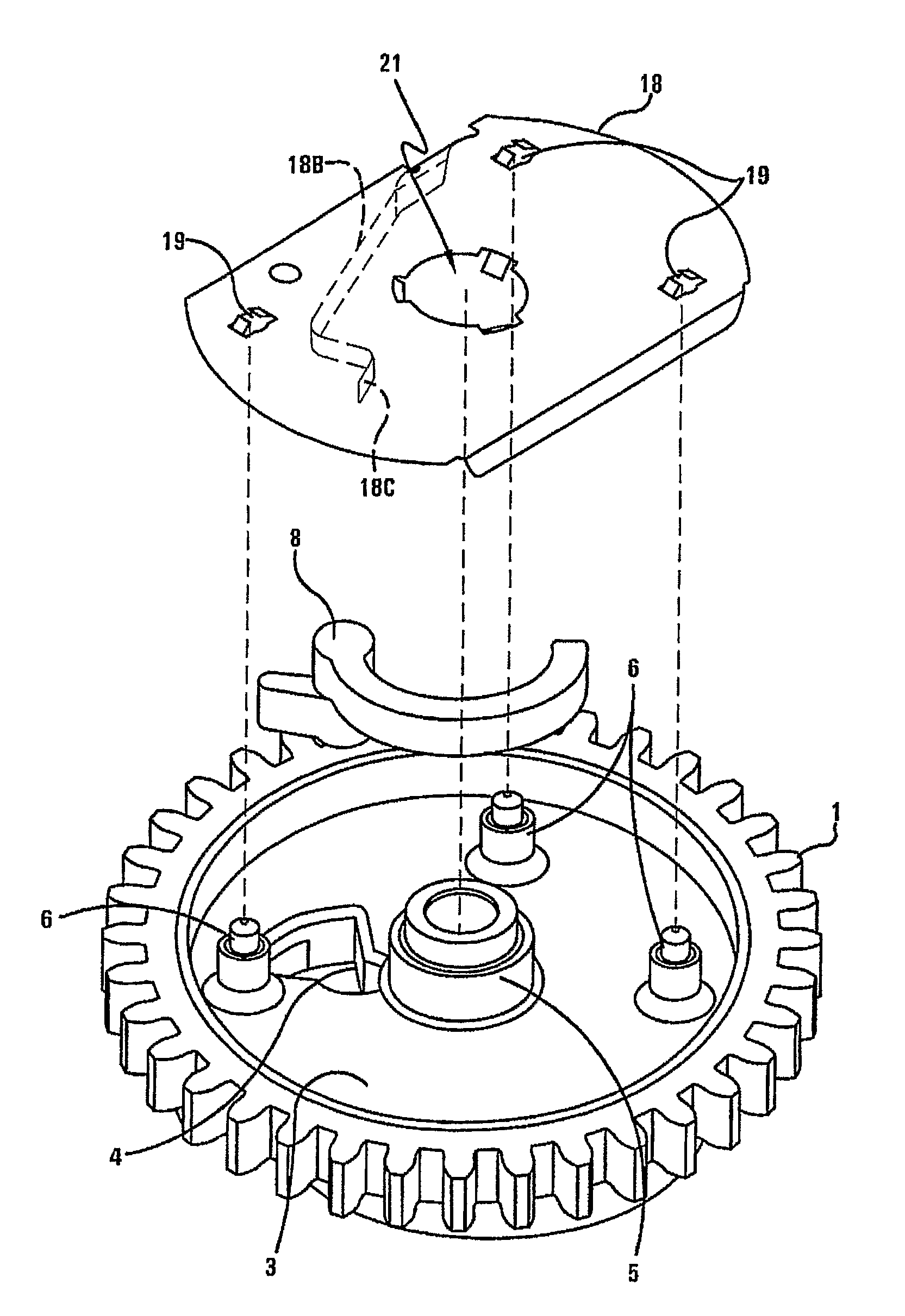
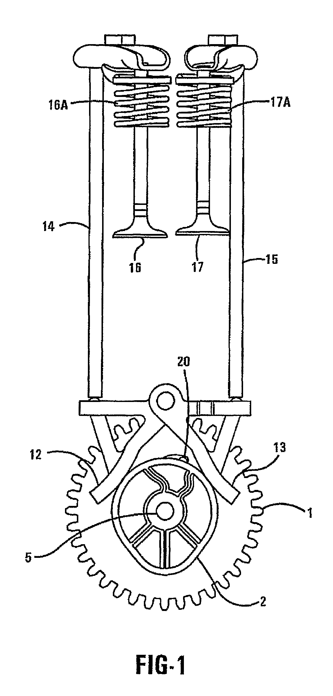
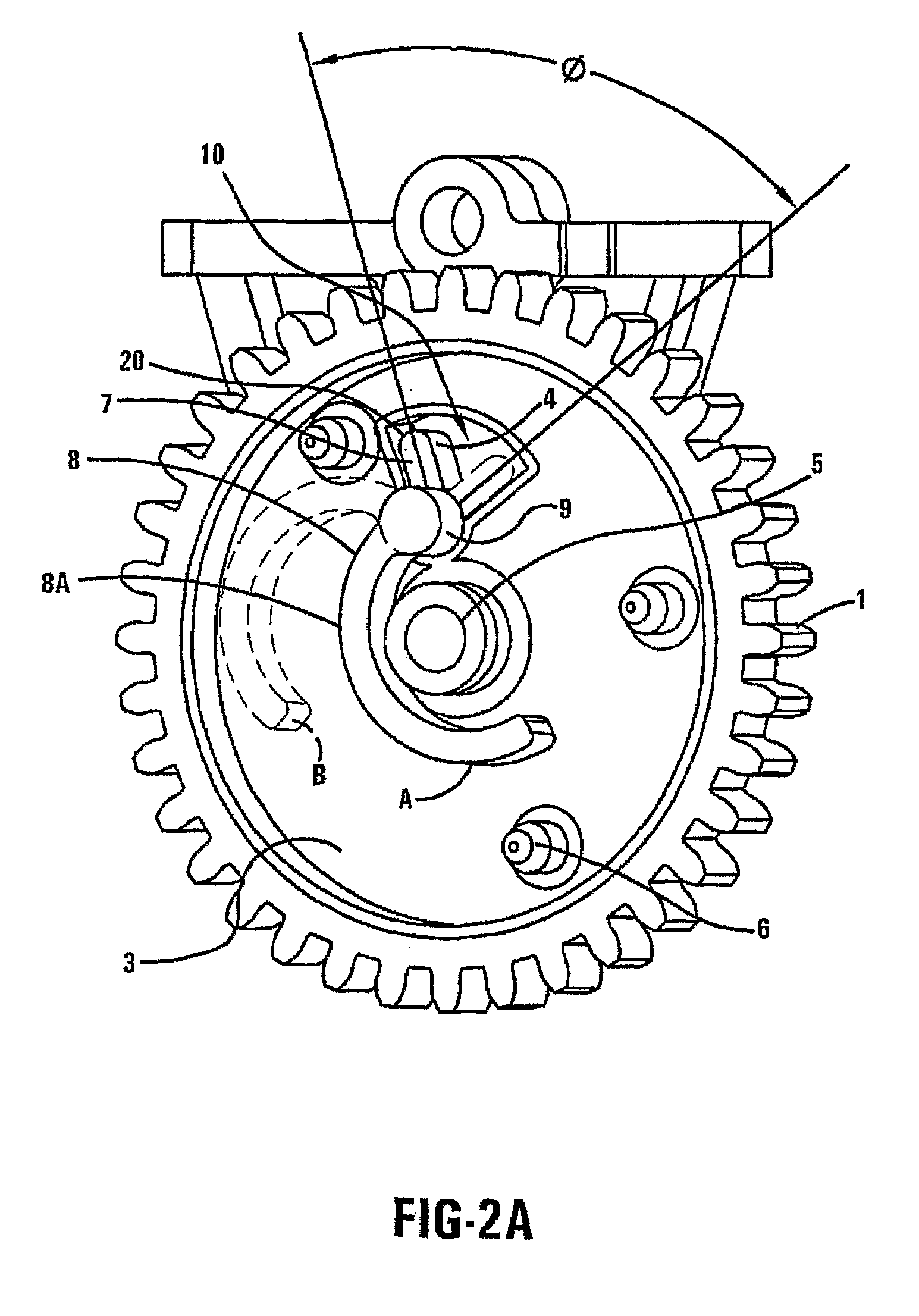
[0022]The present invention pertains to an automatic decompression mechanism for selectively opening a cylinder valve of an engine so as to reduce the external starting force required to rotate the engine shaft during the starting cycle of the engine. In accordance with an exemplary embodiment of the present invention, the exhaust valve of an internal combustion (IC) engine is opened slightly and temporarily during the compression s...


PUM

PropertyMeasurementUnit
angleaaaaaaaaaa
compression pressureaaaaaaaaaa
weightaaaaaaaaaa

Abstract

An automatic decompression mechanism for selectively actuating a cylinder valve of an engine so as to reduce the starting force required to start the engine. The mechanism includes a cam gear, a centrifugal member, and a cover member comprising an integrally formed biasing means for biasing and retaining the centrifugal member in the cam gear. The biasing means urges the centrifugal member into a decompression position when the cam gear is rotating at a lower speed, wherein a projecting portion of the centrifugal member actuates the valve mechanism to reduce the starting force required to start the engine. During normal engine operation, the centrifugal member pivots into a non-decompression position wherein the projecting portion of the centrifugal member recedes below the cam profile surface so as to prevent the projecting portion from actuating the valve mechanism.

Description

CROSS-REFERENCE TO RELATED APPLICATION[0001]The present application claims priority under 35 U.S.C. §119(e) to U.S. Provisional Patent Application No. 60 / 669,654, filed Apr. 8, 2005.BACKGROUND OF THE INVENTION[0002]1. Field of Invention[0003]The present invention relates to a decompression mechanism for an engine, and more particularly relates to an automatic decompression mechanism for an internal combustion engine. The automatic decompression mechanism selectively actuates a cylinder valve of the engine so as to reduce the compression pressure in the combustion chamber during starting of the engine, with results being that the starting force required to start the engine is reduced.[0004]2. Description of Related Art[0005]Automatic decompression mechanisms are typically employed in internal combustion (IC) engines to provide improved engine performance at a variety of engine speeds. Known mechanisms typically include a pivoting centrifugal component capable of varying an outside ca...

Claims


Application Information

Patent Timeline
Patent Type & Authority Patents(United States)
IPC IPC(8): F01L13/08
CPCF01L13/085Y10T29/49826
Inventor KRUEGER, ERIK P.
Owner MTD PRODUCTS
Why Eureka
Try Eureka