Support means

a technology of supporting means and supports, which is applied in the direction of conveyor parts, loading/unloading, transportation and packaging, etc., can solve the problems of not being able to provide foldable support beams for the head section, the path of the conveyor head section from the working position to the transport position is relatively complicated, and the conveyor head section is subject to high stress. , to achieve the effect of convenient maintenance and repair

Active Publication Date: 2009-06-30
SANDVIK INTELLECTUAL PROPERTY AB
View PDF19 Cites 16 Cited by
  • Summary
  • Abstract
  • Description
  • Claims
  • Application Information

AI Technical Summary

Benefits of technology

[0034]By enabling the support means to move in this manner, greater flexibility of positioning and movement of the support means may be available and therefore the length of the support means can be extended in comparison to prior art plant whilst still allowing the support means to lie within the permissible dimensions of the plant when the conveyor is in a transit position. Furthermore, as the length of the support means can be increased from the known plant, the length of the conveyor itself can be increased thereby allowing for a higher stockpile and higher capacity of the plant.
[0044]Fine adjustment of the length of the mounting arm may provide for adjustment of tracking of a conveyor belt carried upon the lateral conveyor. Such tracking adjustment can be carried out from ground level whilst the conveyor is operating thereby avoiding downtime of the plant and subsequent loss of production.
[0069]According to a fifth aspect of the present invention, there is provided a support means for supporting a lateral conveyor adapted for mounting upon a mobile chassis, said conveyor comprising of tail section, middle section and at least one head section having pivot points related to the conveyor frame separating said sections from each other, said supporting means comprising a variable length mounting arm, said mounting arm comprising a first end and a second end, means for locking the length of the variable length mounting arm into at least one fixed length corresponding to the length of the conveyor in the working position, one end being fixed to said mobile chassis or a part fixed immobile in relation to said mobile chassis, said other end of the mounting arm being fixed to the said head section of the conveyor or a part fixed immobile in relation to the said head section of the conveyor via a joint allowing three degrees of freedom of movement of the mounting arm with respect to the head section of the conveyor.
[0084]According to a seventh aspect of the present invention, there is provided a support means for supporting a lateral conveyor adapted for mounting upon a mobile chassis, said conveyor comprising of tail section, middle section and at least one head section having pivot points related to the conveyor frame separating said sections from each other, said supporting means comprising a variable length mounting arm, said mounting arm comprising a first end and a second end, means for locking the length of the variable length mounting arm into at least one fixed length corresponding to the length of the conveyor in the working position, one end being fixed to the said head section of the conveyor or a part fixed immobile in relation to the said head section of the conveyor, said other end of the mounting arm being fixed to said mobile chassis or a part fixed immobile in relation to said mobile chassis via a joint allowing three degrees of freedom of movement of the mounting arm with respect to the head section of the conveyor.
[0086]According to an eighth aspect of the present invention there is provided a support means for supporting a lateral conveyor adapted for mounting upon a mobile chassis, said conveyor comprising of tail section, middle section and at least one head section having pivot points related to the conveyor frame separating said sections from each other; said supporting means comprising a variable length mounting arm said mounting arm comprising a first end and a second end means for locking the length of the variable length mounting arm into at least one fixed length corresponding to the length of the conveyor in the working position one end being fixed to said mobile chassis or a part fixed immobile in relation to said mobile chassis characterised in that said other end of the mounting arm is fixed to the said head section of the conveyor or a part fixed immobile in relation to the said head section of the conveyor and adjustment means are provided to finely alter the length of the mounting arm when locked into the at least one fixed length.

Problems solved by technology

While the manner in which the lateral conveyors are connected to the plant is relatively simple for the operating position, major problems arise in ensuring that the overall width and height of the mobile plant is within certain dimensions when carrying such conveyors during transport.
Another problem is ensuring safety, on-site, in movement of the lateral conveyors to a position for transport of the mobile plant.
A further problem lies in the support of the lateral conveyors during operation and when travelling inside the worksite with the conveyors in the working position: the conveyors are subject to high stresses due to their own weight, the weight of the screened material on the belt and vibrations caused by uneven and / or soft soil at the worksite.
A still further problem is that of providing for easy and safe maintenance or repair of the lateral conveyors on-site or at a workshop.
So far, it has been a problem, to easily and effectively support such foldable conveyors.
In EP 0641 607B the path of the head section of the conveyor from the working position to the transport position is relatively complicated.
So far it has not been possible to provide foldable support beams for the head section, which is easy to use and does not challenge the permissible transport dimensions of the plant.
Anyhow, this sort of support leaves the head section unsupported, which makes the conveyors subject to high stresses due to their own weight, the weight of the screened material on the belt and vibrations caused by uneven and / or soft soil at the worksite while working or travelling inside the worksite with the conveyors in the working position.
However, this would challenge the transportation height of the plant.
Also detachable, non-foldable, supports between the conveyor's head section and the plant chassis and / or the ground have been used: these have proved to be difficult to use or even dangerous in situations where the support has detached itself accidentally.
A still further problem is that of providing for easy and safe maintenance or repair of the lateral conveyors on-site or at a workshop.
A safe way of reaching these parts has proved illusive as they are quite high and ground in the worksite is usually soft or uneven, which makes it dangerous to work using ladders.
More safe equipment helping the service people to reach high is not often available in the worksites.

Method used


Image

  • Support means
  • Support means
  • Support means

Examples


Embodiment Construction

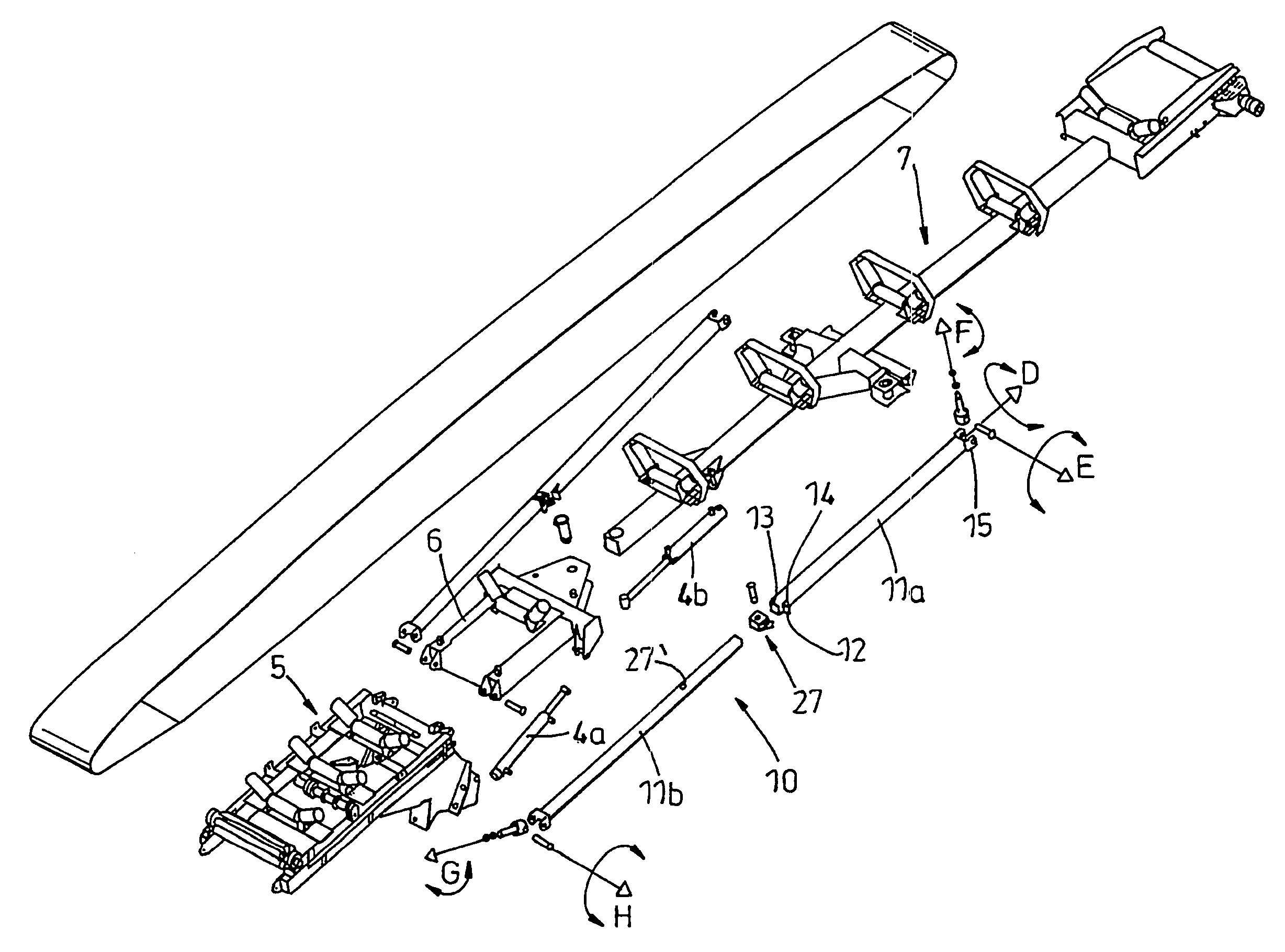
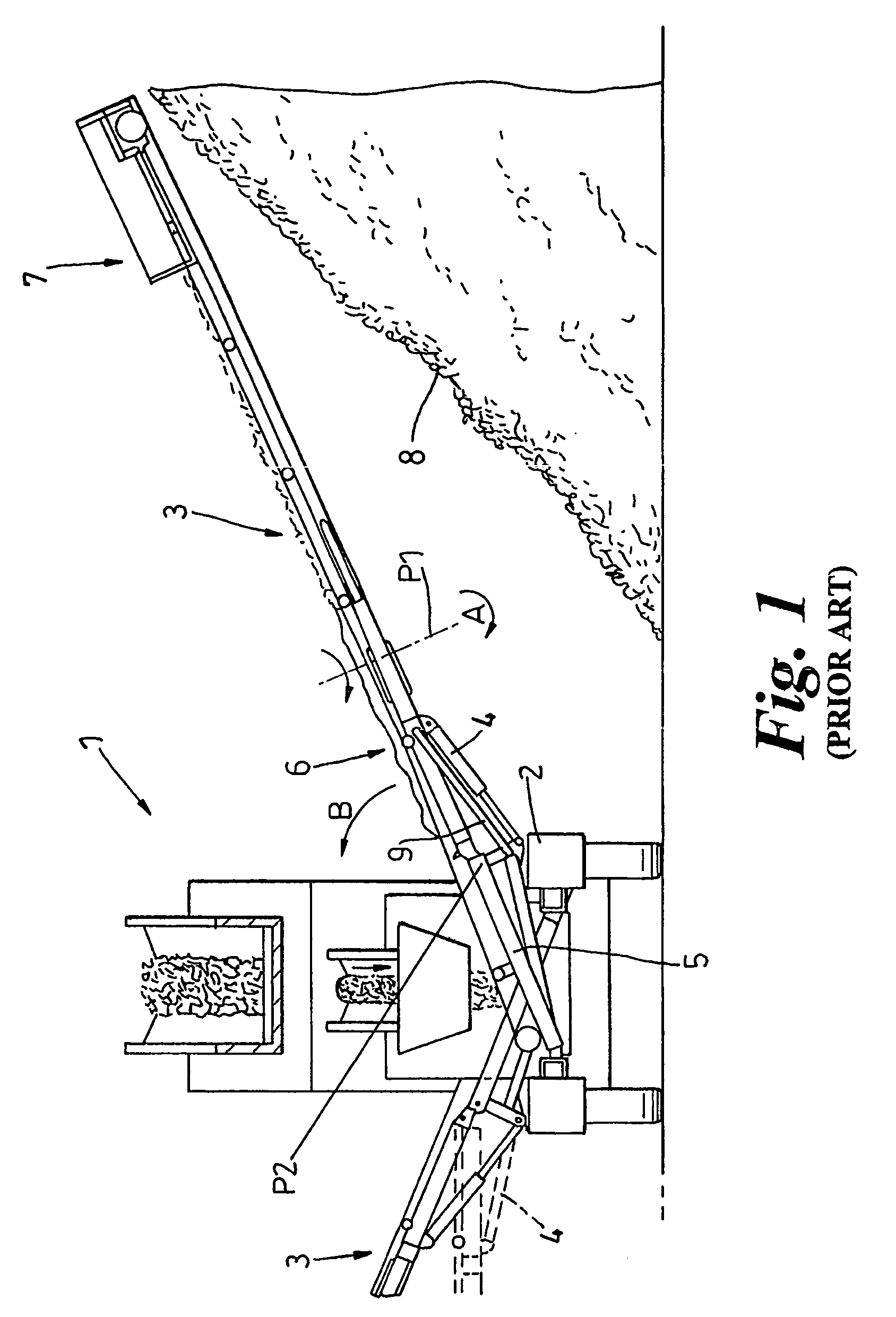
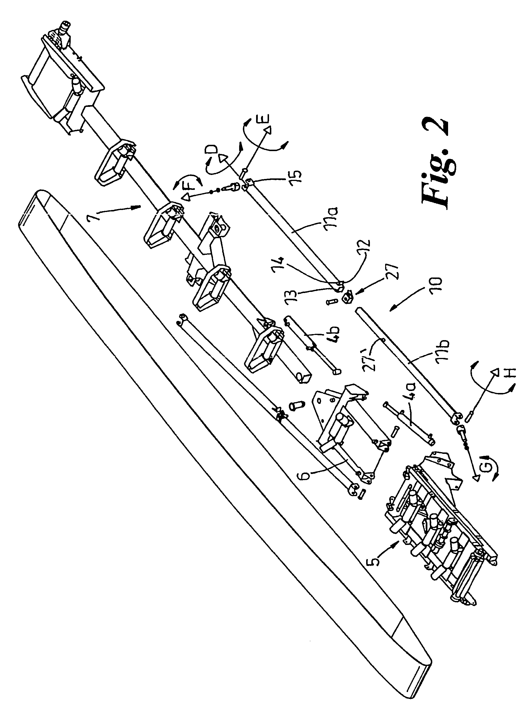
[0098]Turning now to the Figures, there is shown in FIG. 1 a known mobile aggregate processing plant 1 which comprises a chassis 2 upon which a pair of lateral conveyors 3 are mounted. The plant comprises a screen (not shown) which distributes the screened material on to the lateral conveyors 3. The plant is shown in FIG. 1 in an end elevation in order to clearly show the lateral conveyors 3 which are mounted on either side of the chassis 2 of the plant.

[0099]Hydraulic rams 4 are operated to extend the conveyors from a stowed position adjacent the chassis for transport to the operating position shown in FIG. 1. The lateral conveyors comprise a tail section 5 adjacent to the chassis 2, a middle section 6 and a head section 7 remote from the chassis 2. The head section of the conveyor is mounted to the middle section through a pivot point P1 such that the head section can pivot around the pivot point as shown by axis A in FIG. 1. Processed material passes along the lateral conveyors f...


PUM


Abstract

The invention relates to support means, which is for supporting a lateral conveyor adapted for mounting upon a mobile chassis, including a tail section, middle section and at least one head section having pivot points related to the conveyor frame separating said sections from each other. The support means includes a variable length mounting arm comprising at least first and second sections and first and second ends, and means for locking the length of the mounting arm into at least one fixed length corresponding to the length of the conveyor in use. The first end is fixed immobile in relation to the mobile chassis and the second end is fixed immobile in relation to the head section of the conveyor. Also, the support means is configured to provide at least three kinematic pairs, a first kinematic pair being formed by the first section and the mobile chassis, a second kinematic pair is formed by the first and second sections, and the third kinematic pair is formed by the second section and the head section of the conveyor and is provided by a joint, the support means being further configured such that the first, second and third kinematic pairs respectively provide for two, one and three degrees of freedom of movement.

Description

CROSS REFERENCE TO RELATED APPLICATIONS[0001]This is the national stage of PCT International application no. PCT / GB2004 / 001922 filed Apr. 30, 2004 and published in English as WO 2004 / 096677 A1 on Nov. 11, 2004 which claims the priority of United Kingdom application no. 0310177.1, filed May 2, 2003, the disclosures of which are hereby incorporated herein by reference.FIELD OF THE INVENTION[0002]This invention relates to improvements in support means for supporting a lateral conveyor particularly adapted for mounting on a mobile, aggregate material processing plant such as screening plant, crushing plant or mining plant, and, more particularly, to improvements in the support arms for supporting a stowable lateral conveyor upon the plant.BACKGROUND OF THE INVENTION[0003]In this specification, the term “aggregate material” means different types of mined or quarried or natural mineral materials, like gravel, sand, ores, coal, different kinds of soil materials like loam and peat, differen...

Claims


Application Information

Patent Timeline
Patent Type & Authority Patents(United States)
IPC IPC(8): B65G21/00B65G41/00
CPCB65G41/002B65G2201/04B65G21/10
Inventor MAKINEN, MARKO KALEVIWHYTE, STEPHEN ALEXANDERANTILA, KARI HEIKKI OLAVI
Owner SANDVIK INTELLECTUAL PROPERTY AB
Why Eureka
Try Eureka