Roll paper printer

a paper printer and roll paper technology, applied in the direction of printing, thin material processing, article delivery, etc., can solve the problems of affecting the loading and removing of the roll paper, and even affecting the detection accuracy of the detection lever

Inactive Publication Date: 2009-06-30
SEIKO EPSON CORP
View PDF22 Cites 47 Cited by
  • Summary
  • Abstract
  • Description
  • Claims
  • Application Information

AI Technical Summary

Benefits of technology

[0014]Opening the operable cover unit of a roll paper printer according to this embodiment of the invention causes the detection lever to move in the retraction direction in which the detection lever retracts from the roll paper compartment. By appropriately setting the distance the detection lever moves in this retraction direction, the roll paper will not contact the detection lever when the roll paper is loaded into the roll paper compartment. In addition, when the detection lever is inserted to the roll paper core because the roll paper is depleted or near the end and the roll is therefore removed, the detection lever will be completely retracted from the core to a position where the detection lever will not interfere with the roll paper, and the roll paper or core can therefore be easily removed. The detection lever is therefore prevented from contacting the roll paper and interfering with the ease of loading or removing roll paper from the roll paper compartment.
[0015]There is also no need to form a tapered or inclined surface on the detection lever so that the roll paper pushes the detection lever smoothly out of the way when loading or removing roll paper. The near-end detection precision of the detection lever can therefore be improved.
[0026]So that the roll paper can be held at a predetermined position inside the roll paper compartment, a recessed channel and sloped guide surfaces for guiding the roll into this channel as the roll diameter decreases are conventionally formed on the bottom of the roll paper compartment. However, forming this recessed channel and sloped guide surfaces increases the vertical size of the roll paper compartment, and thus impedes reducing the size of the printer. This is particularly disadvantageous for reducing the height of a printer having an operable cover unit disposed to the front of the printer to pivot at the bottom and open to the front of the printer so that the roll paper can be replaced in the roll paper compartment from the front of the printer.
[0028]The arrangement of the present invention does not require rendering such a recessed channel and sloped guide surfaces on the bottom of the roll paper compartment, and enables the bottom of the roll paper compartment to be flat. The invention therefore reduces the increase in the height of the roll paper printer while still holding the roll paper at a predetermined position in the roll paper compartment so that the near-end of the roll paper can be reliably detected.
[0030]This arrangement avoids the problem of not being able to completely close the operable cover unit because the detection lever protrudes into the roll paper compartment before the roll paper is stored in the roll paper compartment when the operable cover unit is closed, and the roll paper becomes held between the front part of the detection lever and the operable cover unit.
[0032]If the roll paper moves to the back inside the roll paper compartment so that the detection lever separates from the end, and the roll paper then moves from the back to the front, this arrangement causes the outside circumference edge of the roll to contact the back-facing tapered surface so that the roll paper can move easily forward while pushing the detection lever in the retraction direction and restore the detection lever to the position pressed against the round end of the roll paper.

Problems solved by technology

If the roll paper is loaded or removed quickly when loading or removing the roll paper, the detection lever may not be able to retract as quickly, resulting in the detection lever catching on the roll paper and interfering with loading and removing the roll paper.
The detection lever may even be damaged.
However, rendering a taper with a large angle on the detection lever causes the problem of a drop in detection precision because setting the point at which the detection lever is inserted to the roll paper core with precision when the roll paper decreases to a predetermined remaining volume is more difficult than with a detection lever that does not have a taper.
The same problem also occurs with a mechanism whereby the detection lever separates to the outside circumference of the roll paper.

Method used


Image

  • Roll paper printer
  • Roll paper printer
  • Roll paper printer

Examples


second embodiment

[0094]A roll paper printer according to a second embodiment of the invention is described next with reference to FIG. 9 to FIG. 16.

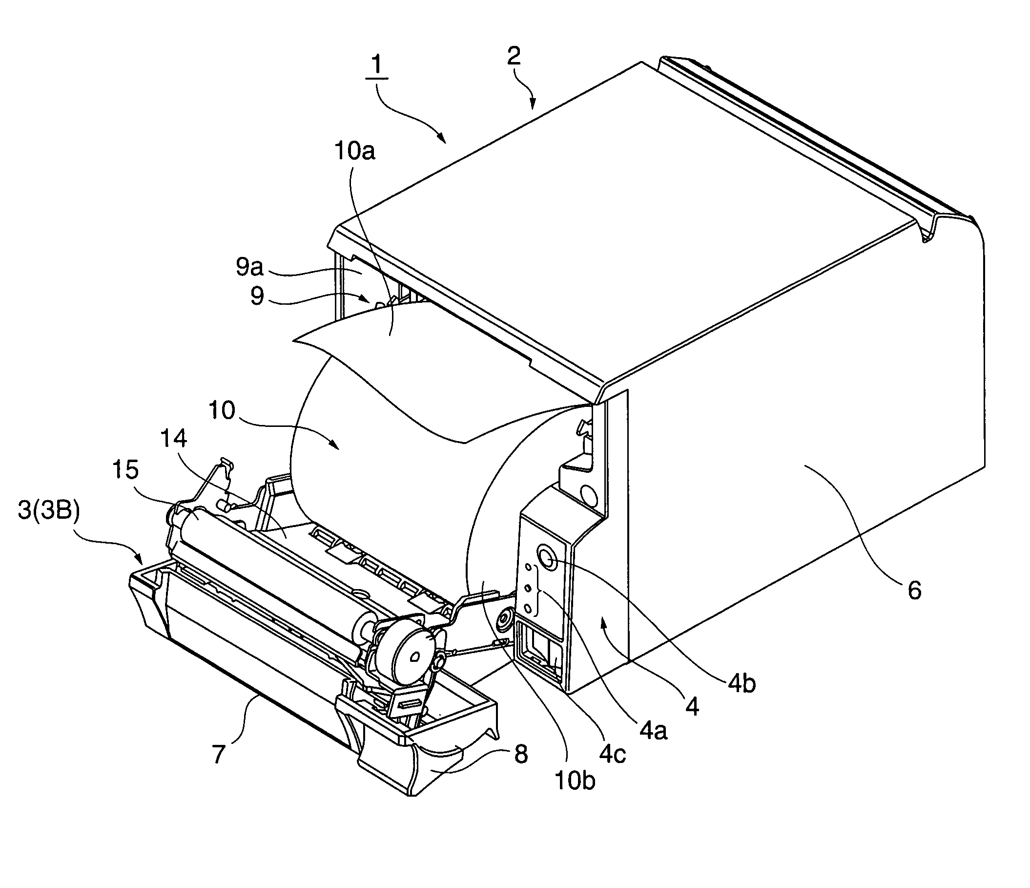
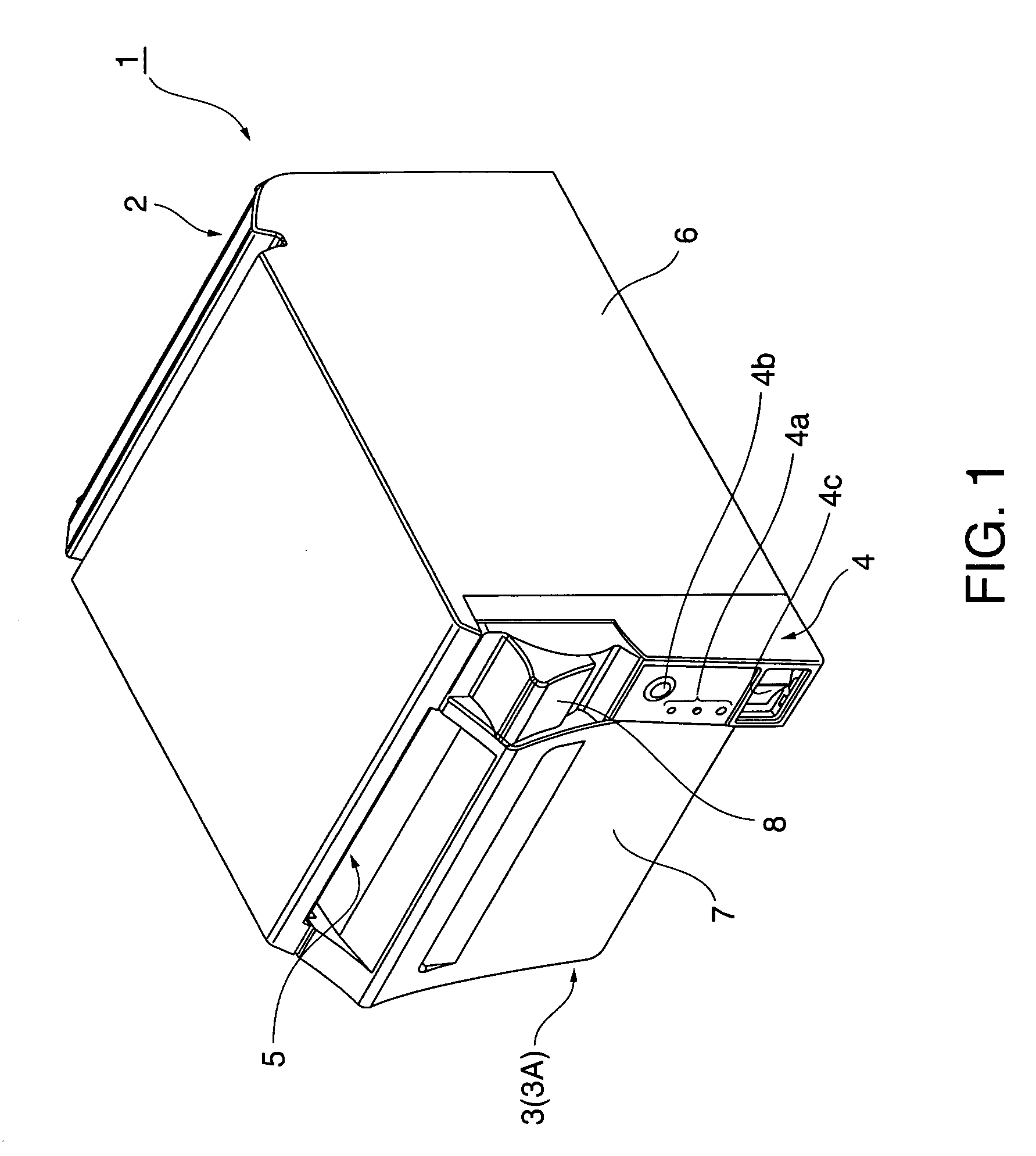
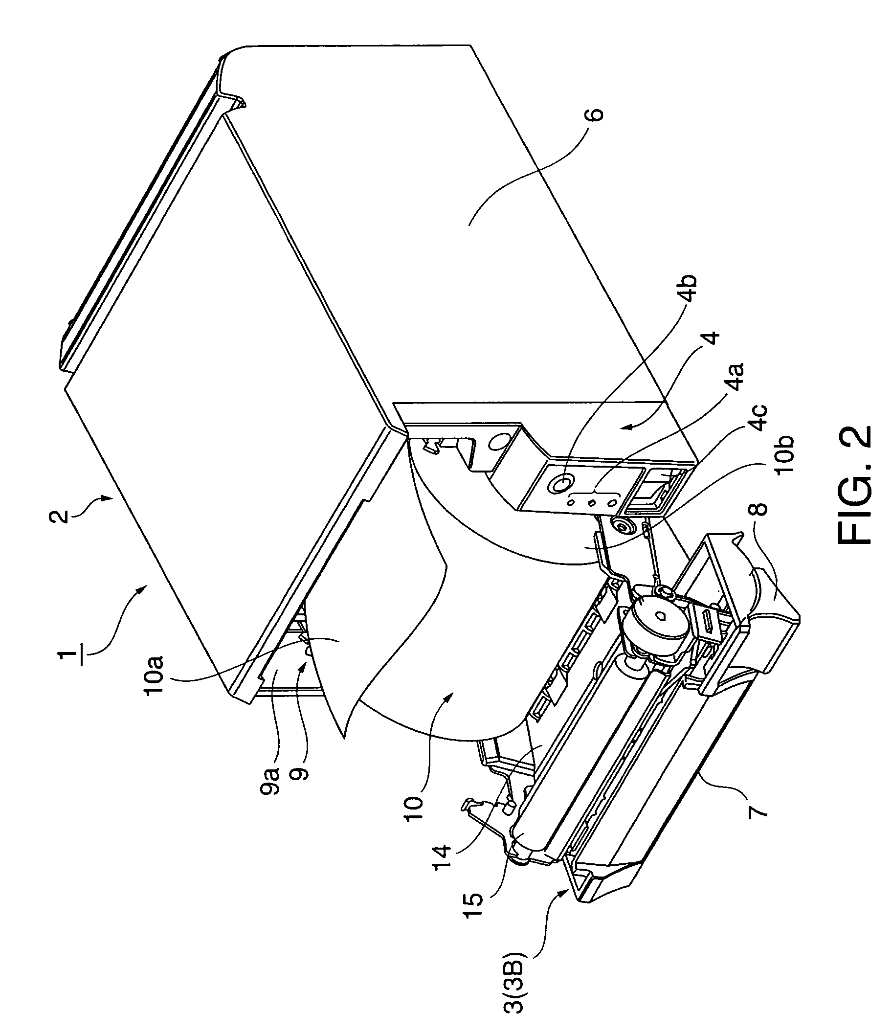
[0095]FIG. 9 is an external oblique view of the roll paper printer, FIG. 10 is an oblique view of the printer mechanism part as seen from the front left, FIG. 11 is an oblique view of the printer mechanism part as seen from the front right, FIG. 12 is an oblique view of the printer mechanism part when the operable cover unit is open, and FIG. 13 is a schematic diagram showing the internal arrangement of the roll paper printer.

[0096]A roll paper printer 100 according to this embodiment of the invention has a printer mechanism unit 200, a printer case 102 covering substantially all of the printer mechanism unit 200, and an operable cover case 103 covering the front of the printer mechanism unit 200 that is not covered by the printer case 102. A paper exit 108 extending widthwise to the operable cover case 103 is formed at the top part of the operable cover...


PUM


Abstract

A roll paper printer comprising a roll paper storage unit having a bottom surface on which a roll paper is held and rolls, an operable cover unit for opening and closing a roll paper loading opening to the roll paper storage unit, a roll paper size detection mechanism comprising a detection lever that can move in a direction protruding into the roll paper storage unit and a direction retracting from the roll paper storage unit, and an urging member for urging the detection lever in the protruding direction, wherein the detection lever separates from the roll paper and is pushed in the protruding direction when an outside diameter of the roll paper stored in the roll paper storage unit decreases to a predetermined size or less, and a detection lever retraction mechanism for moving the detection lever protruding into the roll paper storage unit in the retracting direction against the urging force of the urging member in conjunction with the operable cover unit opening.

Description

[0001]The present invention claims benefit from Japanese Application Nos. 2005-230398 filed on Aug. 9, 2005 and 2005-355738 filed on Dec. 9, 2005, which are hereby incorporated by reference in its entirety.BACKGROUND OF THE INVENTION[0002]1. Field of Technology[0003]The present invention relates to a roll paper printer having a roll paper size detection device featuring improvement enabling easy replacement of the roll paper.[0004]2. Description of Related Art[0005]One type of roll paper printer has the roll paper loaded so that the roll paper can simply roll on the bottom of the roll paper compartment. The roll paper typically has a long tape of recording paper wound into a roll on a hollow core that has a hole in the center. This type of roll paper printer also commonly has a roll paper size detection device for detecting the near-end of the roll when there is little roll paper left on the core. One type of roll paper size detection device has a lever that is inserted to the hole ...

Claims


Application Information

Patent Timeline
Patent Type & Authority Patents(United States)
IPC IPC(8): B41J15/00B65H16/02B65H26/08
CPCB41J11/0075B41J15/04B41J29/02B41J29/13B41J29/48
Inventor MAEKAWA, HIRONORIMOMOSE, JIROSHIROTORI, MOTOYOSHI
Owner SEIKO EPSON CORP
Why Eureka
Try Eureka