Pump for pumping high-viscosity liquids, slurries, and liquids with solids

a technology of liquids and apparatuses, applied in the direction of liquid fuel engines, rotors, machines/engines, etc., can solve the problems of reducing affecting the quality of the fluid they pump, so as to reduce slippage and dead zones.

a technology of liquids and apparatuses, applied in the direction of liquid fuel engines, rotors, machines/engines, etc., can solve the problems of reducing affecting the quality of the fluid they pump, so as to reduce slippage and dead zones.

US7553124B1Inactive Publication Date: 2009-06-30JIMENEZ JUAN

Image

  • Pump for pumping high-viscosity liquids, slurries, and liquids with solids
  • Pump for pumping high-viscosity liquids, slurries, and liquids with solids
  • Pump for pumping high-viscosity liquids, slurries, and liquids with solids

Examples


first embodiment

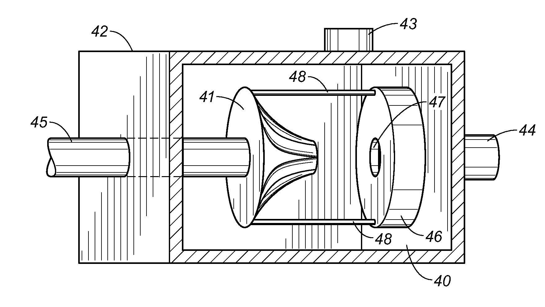
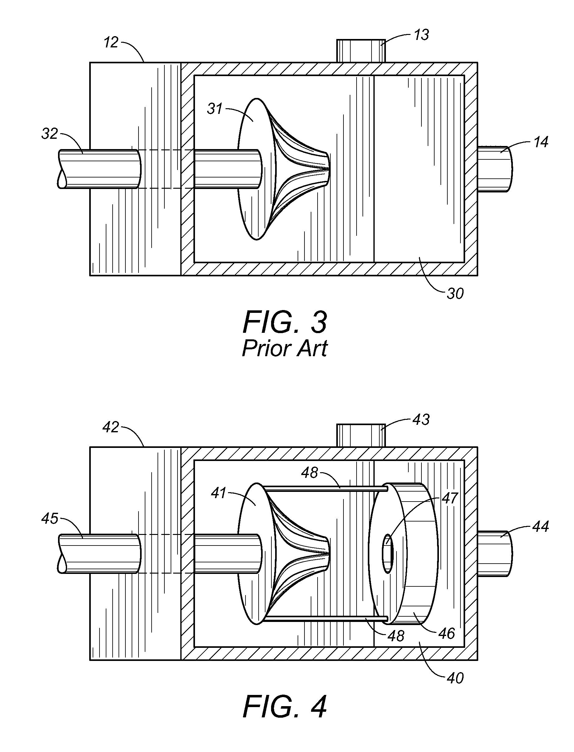
[0033]FIG. 4 shows a cut-away view of the housing of the present invention. The housing 42 has a chamber 40 with inlet 44 and outlet 43. The present invention utilizes an impeller 41 driven by a drive shaft 45. The impeller 41 is a recessed impeller which is connected via ⅜″ rods 48 to a disc impeller 46. The disc impeller 46 has a hole 47 in the center so as to allow HVF to flow therethrough. The recessed impeller 41 and disc impeller 46 together rotate so as to pump HVF out of the chamber 40 through the outlet 43.

second embodiment

[0034]FIG. 5 shows a cut-away view of the housing of the present invention. The housing 52 has a chamber 50 with inlet 54 and outlet 53. The present invention utilizes an impeller 51 driven by a drive shaft 55. The impeller 51 is a recessed impeller which is connected via ⅜″ rods 58 to a second impeller 56. The second impeller 56 is also a recessed impeller. The two impellers 51 and 56 face each other. The second impeller 56 also has a hole 57 in the center so as to allow HVF to flow therethrough. The recessed impeller 51 and recessed impeller 56 together rotate so as to pump HVF entering the inlet 54 out of the chamber 50 through the outlet 53.

third embodiment

[0035]FIG. 6 shows a cut-away view of the housing of the present invention. The housing 62 has a chamber 60 with inlet 64 and outlet 63. The present invention utilizes an impeller 61 driven by a drive shaft 65. The impeller 61 is a half-regular closed impeller which is connected via ⅜″ rods 68 to another half regular closed impeller 66. Both impeller 61 and impeller 66 have vanes 69. Impeller 61 and impeller 66 face each other. Impeller 66 also has a hole 67 in the center so as to allow HVF to flow therethrough. Impeller 61 and impeller 66 together rotate so as to pump HVF entering the inlet 64 out of the chamber 60 through the outlet 63.


PUM


Abstract

The present invention is a centrifugal pump that pumps high-viscosity liquids, slurries, and solids-containing liquids. The pump has a housing, a chamber formed within the housing, a first discoidal member positioned in the chamber, a second discoidal member positioned in that chamber, connecting rods connecting a periphery of the first discoidal member to a periphery of the second discoidal member, and a drive for rotating the first discoidal member and the second discoidal member positioned in the chamber. The first discoidal member is either a recessed impeller or half-regular closed centrifugal impeller. The second discoidal member is a recessed impeller, a disc impeller, or a half-regular closed centrifugal impeller. The second discoidal member has a hole in the center.

Description

RELATED U.S. APPLICATIONS[0001]Not applicable.STATEMENT REGARDING FEDERALLY SPONSORED RESEARCH OR DEVELOPMENT[0002]Not applicable.REFERENCE TO MICROFICHE APPENDIX[0003]Not applicable.FIELD OF THE INVENTION[0004]The present invention relates to an apparatus for pumping high-viscosity liquids, slurries and liquids with solids. More particularly, the present invention combines discoidal members of a centrifugal pump located in the pump housing so as to create a centrifugal pump that has better efficiency and lower maintenance cost than current pumps while pumping high-viscosity liquids, slurries and liquids with solids.BACKGROUND OF THE INVENTION[0005]This invention relates generally to pumps for the handling of high viscosity liquids, slurries, and liquids with solids, collectively referred to as high-viscosity fluids (HVFs). Centrifugal pumps may be used for pumping HVFs; however, traditional centrifugal pumps have problems with cavitation, clogging, binding, and high wear when used ...

Claims


Application Information

Patent Timeline
30 Jun 2009
Publication
US7553124B1
IPC
F01D3/02; F01D13/02
CPC
F04D5/00; F04D5/001; F04D29/2244
Inventors
JIMENEZ, JUAN