Eureka AIR delivers breakthrough ideas for toughest innovation challenges, trusted by R&D personnel around the world.

Method, apparatus, and system for bracing a knee

a knee and knee joint technology, applied in the field of knee braces, can solve problems such as lateral dislocations, and achieve the effects of enhancing patellar function, enhancing proper positioning of the brace, and maximizing the function of proper patellar function

Inactive Publication Date: 2009-06-30
CADICHON GREGORY
View PDF25 Cites 36 Cited by
  • Summary
  • Abstract
  • Description
  • Claims
  • Application Information

AI Technical Summary

Benefits of technology

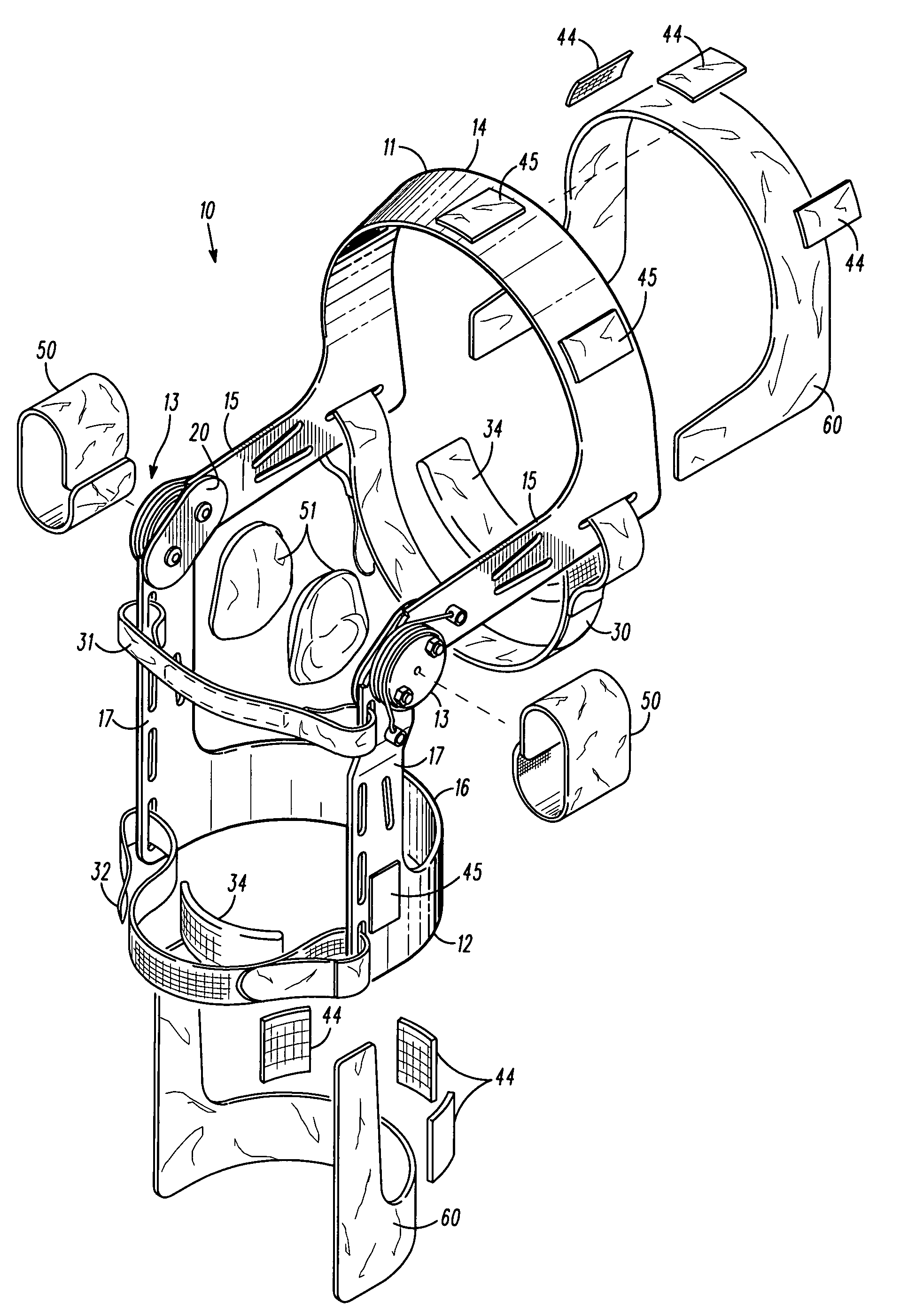
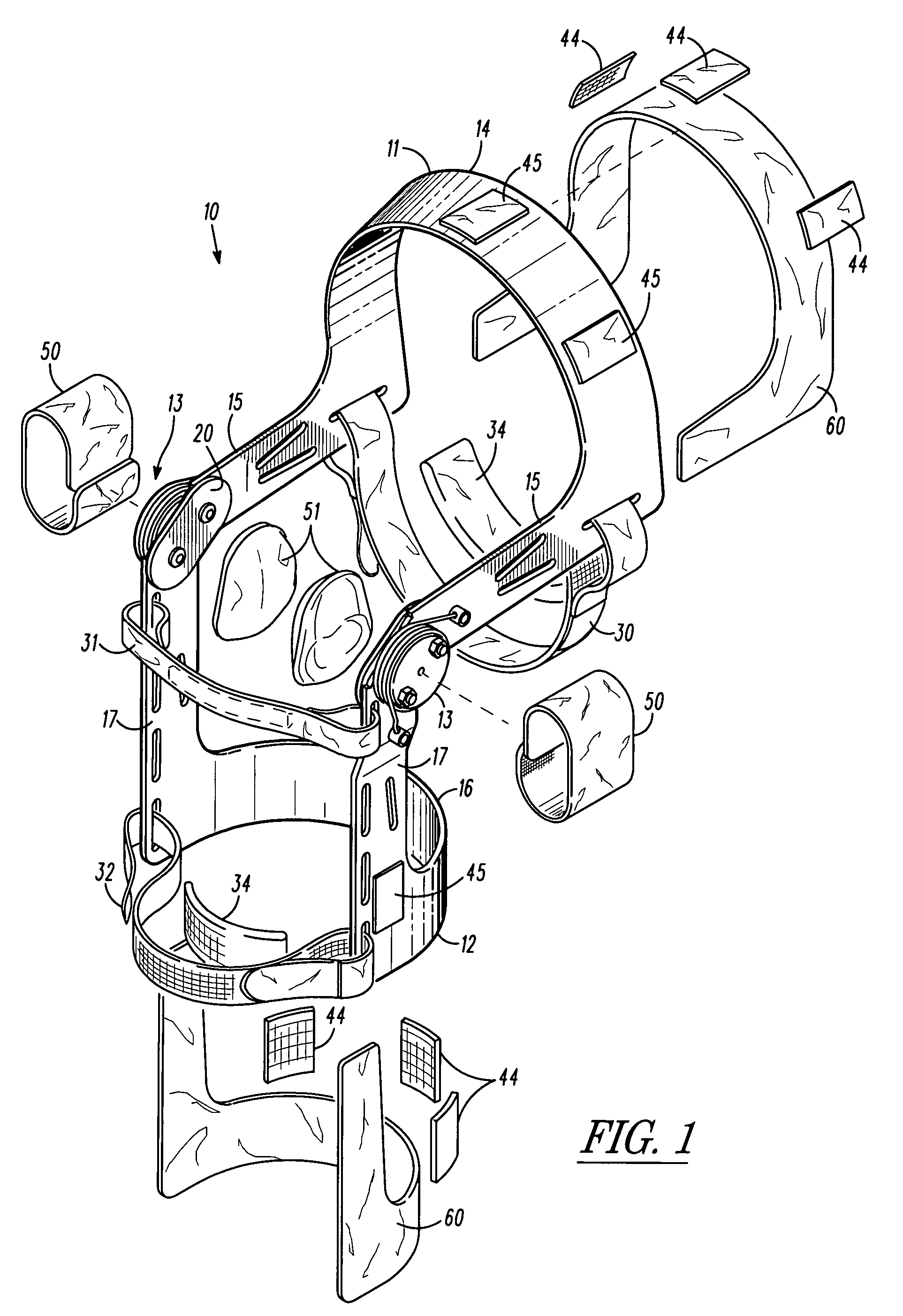
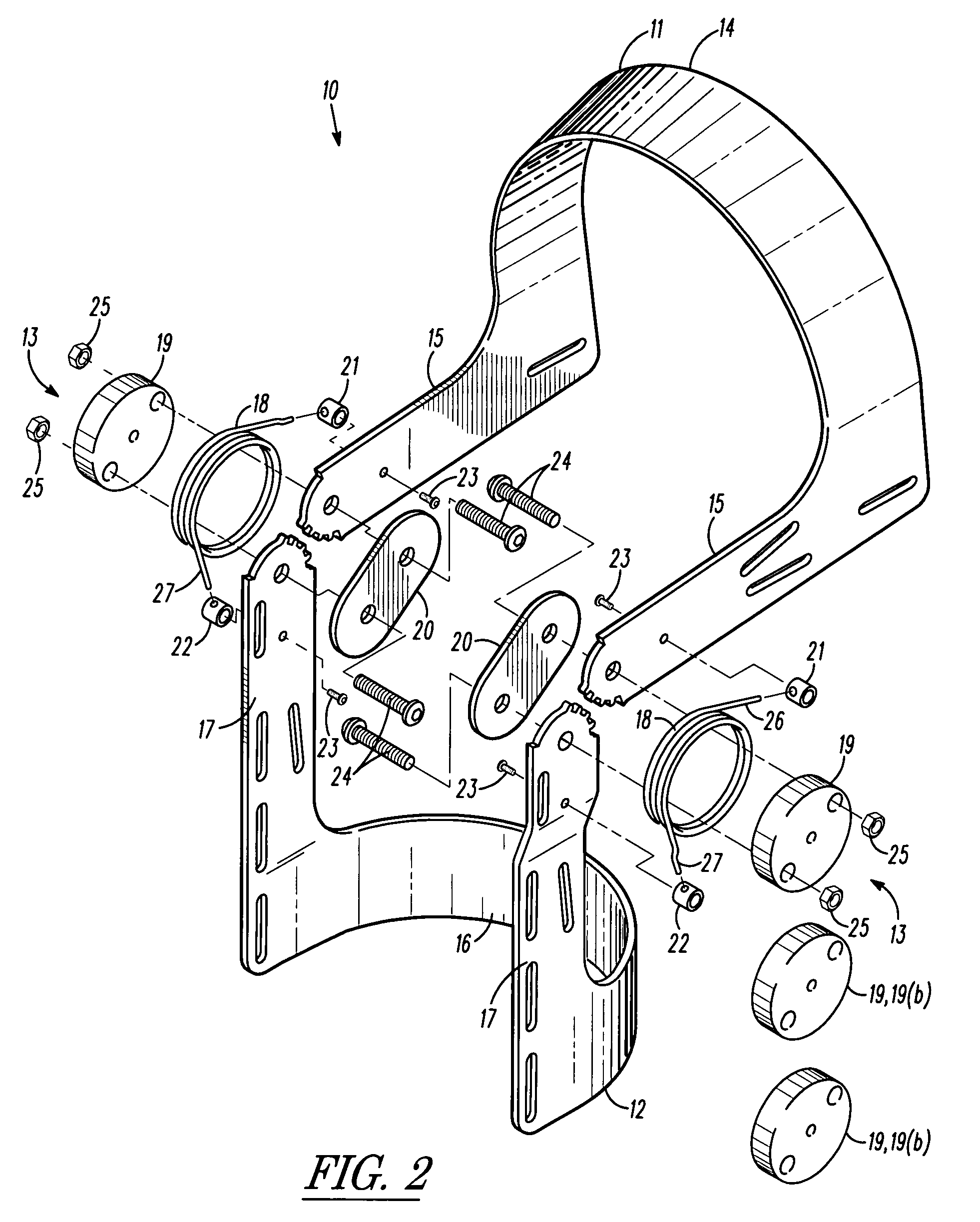
"The present invention provides a knee brace that can improve patellar function by extensionally centering it. The knee brace comprises an upper bracket assembly, a lower bracket assembly, and a pair of torsional spring assemblies. The upper bracket assembly has a U-shaped proximal-anterior-leg-receiving bracket portion, a proximal-medial support arm, and a proximal-lateral support arm. The lower bracket assembly has a U-shaped distal-posterior-leg-receiving bracket portion, a distal medial support arm, and a distal-lateral support arm. The torsional spring elements each have a proximal and distal leg and are designed to compress and release during knee extension. The knee brace is attached to a user's leg and a leg-covering garment, which helps position it correctly for optimal function. The methodology involves damping the torsional spring elements, bracing the upper and lower legs, and actuating the damped spring elements during knee extension to enhance quadriceps muscle contraction and reduce patellar joint stress."

Problems solved by technology

Lateral dislocations do occur, however, given knee injury and other abnormal knee developments.

Method used


Image

  • Method, apparatus, and system for bracing a knee
  • Method, apparatus, and system for bracing a knee
  • Method, apparatus, and system for bracing a knee

Examples


Embodiment Construction

)

[0044]Referring now to the drawings, it is contemplated that the present invention inherently teaches a method, apparatus, and system for bracing a knee joint whereby the braced knee may be extended via enhanced contractual quadriceps action for extensionally centering and enhancing patellar function. It is noted that the patella 100 or kneecap is a thick, triangular bone which articulates with the femur and covers and protects the front of the knee joint as generally depicted and referenced in FIGS. 4-7. The patella 100 is attached to the tendon 101 of the quadriceps femoris muscle, which contracts to straighten or coaxially align the leg as further referenced in the noted figures.

[0045]The vastus intermedialis muscle is attached to the base of patella 100. The vastus lateralis and vastus medialis 102 are attached to lateral and medial borders of patella 100 respectively. It should be further noted that the patella 100 is stabilized by the insertion of vastus medialis 102 and the ...


PUM


Abstract

A knee brace functions to extensionally center and thereby enhance patellar function. The brace comprises an upper bracket assembly, a lower bracket assembly, and certain torsional spring assemblies. The upper and lower bracket assemblies comprise leg-receiving bracket portions and certain axial support structure extending from the bracket portions to bracket junctions. Each spring assembly comprises a torsional spring element and an elastically compressible core element. The torsional spring elements compressibly receive the core elements. The torsional spring elements are actuable for imparting restorative resistance forces, and the core elements function to damp the restorative resistance forces. The damped restorative resistance forces function to safely enhance quadriceps muscle contraction during knee extension. The enhanced quadriceps muscle contraction functions to center the patella during knee extension, and thereby enhance patellar function. The brace may be attached to an anchored leg-covering garment for further restricting axial displacement relative to the leg.

Description

BACKGROUND OF THE INVENTION[0001]1. Field of the Invention[0002]The present invention generally relates to a knee brace. More particularly, the present invention relates to a knee brace for enhancing quadriceps muscle contraction during knee extension for centering the patella and thus enhancing patellar function.[0003]2. Description of the Prior Art[0004]As noted in U.S. Pat. No. 6,540,708 ('708 patent), the physiological motion of the human knee involves complex dynamic motion. Prior art knee bracing apparatuses and systems have attempted to control or otherwise manage the complex motions associated with knee extension, knee flexion, as well as polycentric motion more fully articulated in the '708 patent. Notably, the patella is typically stabilized by the insertion of the vastus medialis and the prominence of the anterior femoral condyles, which normally prevent lateral dislocation of the patella during flexion. Lateral dislocations do occur, however, given knee injury and other ...

Claims


Application Information

Patent Timeline
Patent Type & Authority Patents(United States)
IPC IPC(8): A61F5/00
CPCA61F5/0123A61F2005/0137A61F2005/0169A61F2005/0197
Inventor CADICHON, GREGORY
Owner CADICHON GREGORY
Why Eureka
Eureka Blog
Learn More