Sensor system with modular optical transceivers

a technology of optical transceivers and sensors, applied in the field of sensor systems, can solve the problems of large detection errors, reduced effectiveness, and large time delays

Active Publication Date: 2009-06-30
LITTON SYST INC
View PDF12 Cites 32 Cited by
  • Summary
  • Abstract
  • Description
  • Claims
  • Application Information

AI Technical Summary

Problems solved by technology

This can result in larger time delays and larger detection errors due to incomplete or inaccurate encounter information.
Accordingly, it has been necessary to increase warhead beamwidths to fill the larger volumes of uncertainty with a consequent reduction in effectiveness.
Unfortunately, these optical sensors require complex and difficult alignments, leading to significant expense, and are vulnerable to error due to misalignment of the optical components comprising the sensor.
Accordingly, the transmitters can be unnecessarily expensive and subject to internal misalignment.

Method used


Image

  • Sensor system with modular optical transceivers
  • Sensor system with modular optical transceivers
  • Sensor system with modular optical transceivers

Examples


Embodiment Construction

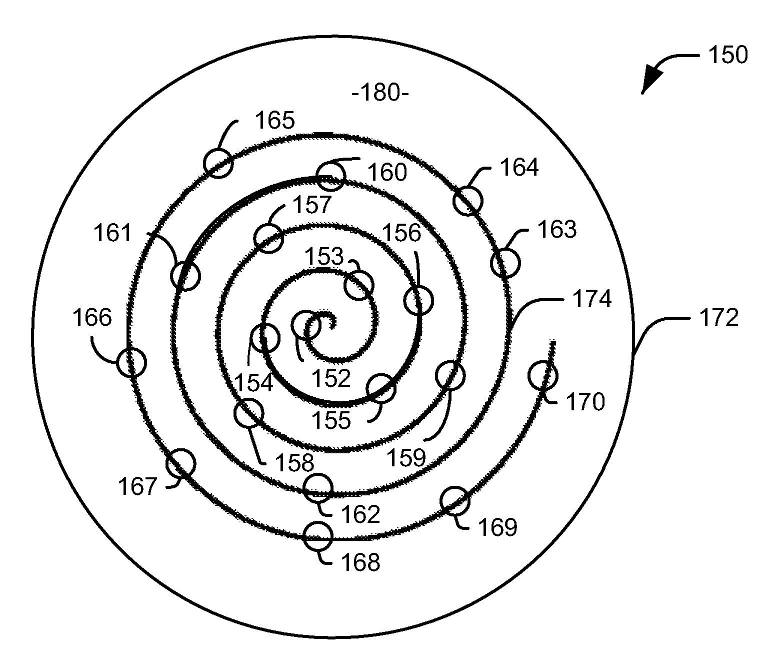
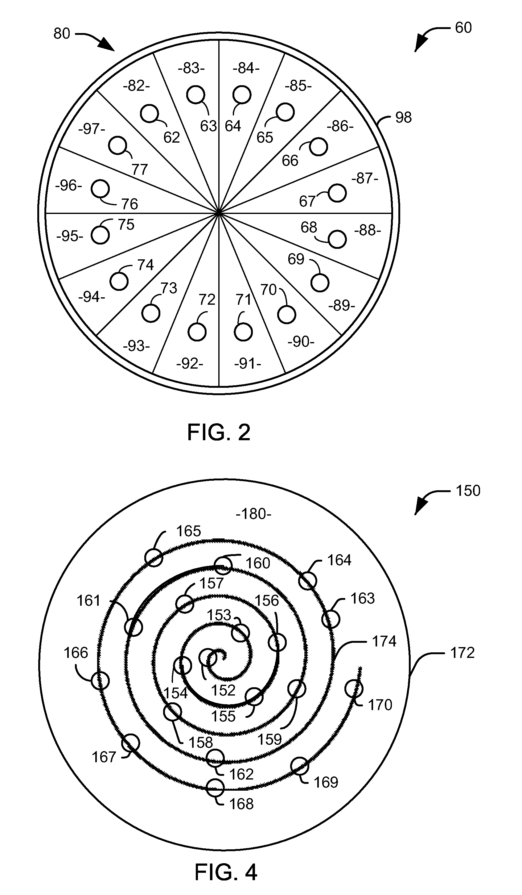
[0015]In accordance with an aspect of the present invention, an optical sensor system can be constructed as a plurality of optical transceiver modules. Each optical transceiver module is self-contained, having both an optical transmitter that emits at least one light beam and one or more detectors aligned as to detect reflected light from the at least one light beam. Each module can be separately aligned, such that misaligned modules can be discarded without the need to discard other transceiver elements of the sensor system. To preserve the intermodule alignment on the sensor, each module can be configured as to be demountably affixed or attached to a carrier, which can be joined together with other carriers to provide an appropriately aligned sensor module. Alternatively, the modules can affix to a frame having appropriate attachment points for receiving the modules. It will be appreciated that this modular approach greatly reduces the complexity of aligning an optical sensor modu...


PUM


Abstract

An optical sensor system and method includes a plurality of optical transceiver modules arranged across the surface of the optical sensor in a predetermined pattern. A given optical transceiver module includes an optical transmitter that produces at least one light beam and an optical receiver that detects reflected light from the at least one light beam. The optical transceiver module further includes housing for housing the optical transmitter and the optical receiver.

Description

TECHNICAL FIELD[0001]The present invention relates to sensor systems and, more particularly, to a sensor system with modular optical transceivers.BACKGROUND OF THE INVENTION[0002]During the last fifty years, missile and target speeds have increased to a great extent, requiring detection and guidance systems associated with automated target recognition systems to be pushed forward. This can result in larger time delays and larger detection errors due to incomplete or inaccurate encounter information. Accordingly, it has been necessary to increase warhead beamwidths to fill the larger volumes of uncertainty with a consequent reduction in effectiveness. Optical fuzing sensors have been proposed to overcome these deficiencies. Unfortunately, these optical sensors require complex and difficult alignments, leading to significant expense, and are vulnerable to error due to misalignment of the optical components comprising the sensor.[0003]FIG. 1 illustrates a prior art fuzing sensor 10. Th...

Claims


Application Information

Patent Timeline
Patent Type & Authority Patents(United States)
IPC IPC(8): G01S7/486G01S17/04
CPCF42C13/02F42C19/06G01S17/026G01S17/04
Inventor WANG, YAUJENIRWIN, BRENDAN J. D.SHORI, RAJ K.
Owner LITTON SYST INC
Why Eureka
Try Eureka