Sensor with optical pressure transducer and method of manufacturing a sensor component

a technology of optical pressure transducer and sensor, which is applied in the direction of interferometer, instruments, diagnostic recording/measuring, etc., can solve the problems of many known differential pressure flow sensor deficiencies

Active Publication Date: 2009-06-30
RIC INVESTMENTS LLC
View PDF19 Cites 12 Cited by
  • Summary
  • Abstract
  • Description
  • Claims
  • Application Information

AI Technical Summary

Problems solved by technology

However, many known differential pressure flow sensors suffer various deficiencies, depending on the application.

Method used


Image

  • Sensor with optical pressure transducer and method of manufacturing a sensor component
  • Sensor with optical pressure transducer and method of manufacturing a sensor component
  • Sensor with optical pressure transducer and method of manufacturing a sensor component

Examples


Embodiment Construction

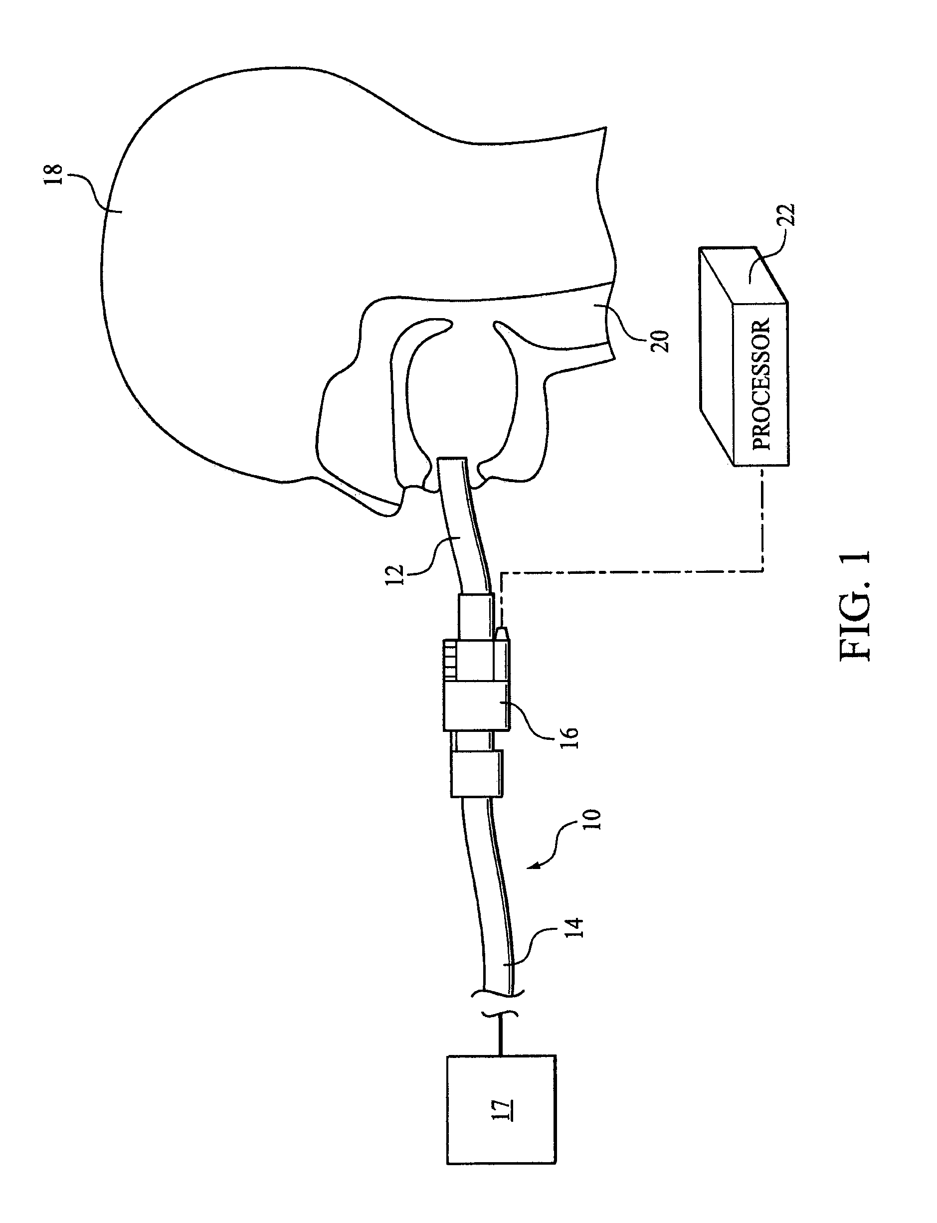
[0038]In FIG. 1 a portion of a respiratory circuit 10 is illustrated according to one embodiment of the invention. Respiratory circuit 10 includes a first end 12, a second end 14, and an airway adaptor 16. Respiratory circuit 10 is adapted to deliver a flow of gas to a patient 18. For example, first end 12 of respiratory circuit 10 includes a patient interface appliance configured to communicate with an airway 20 of patient 18. Some examples of the patient interface appliance may include, for example, an endotracheal tube, a nasal canula, a tracheotomy tube, a mask, or other patient interface appliances. Second end 14 of respiratory circuit 10 is configured to communicate with a source of gas 17. For instance, the source of gas may include ambient atmosphere, a wall gas, a pressure support device, a ventilator, or other sources of gas.

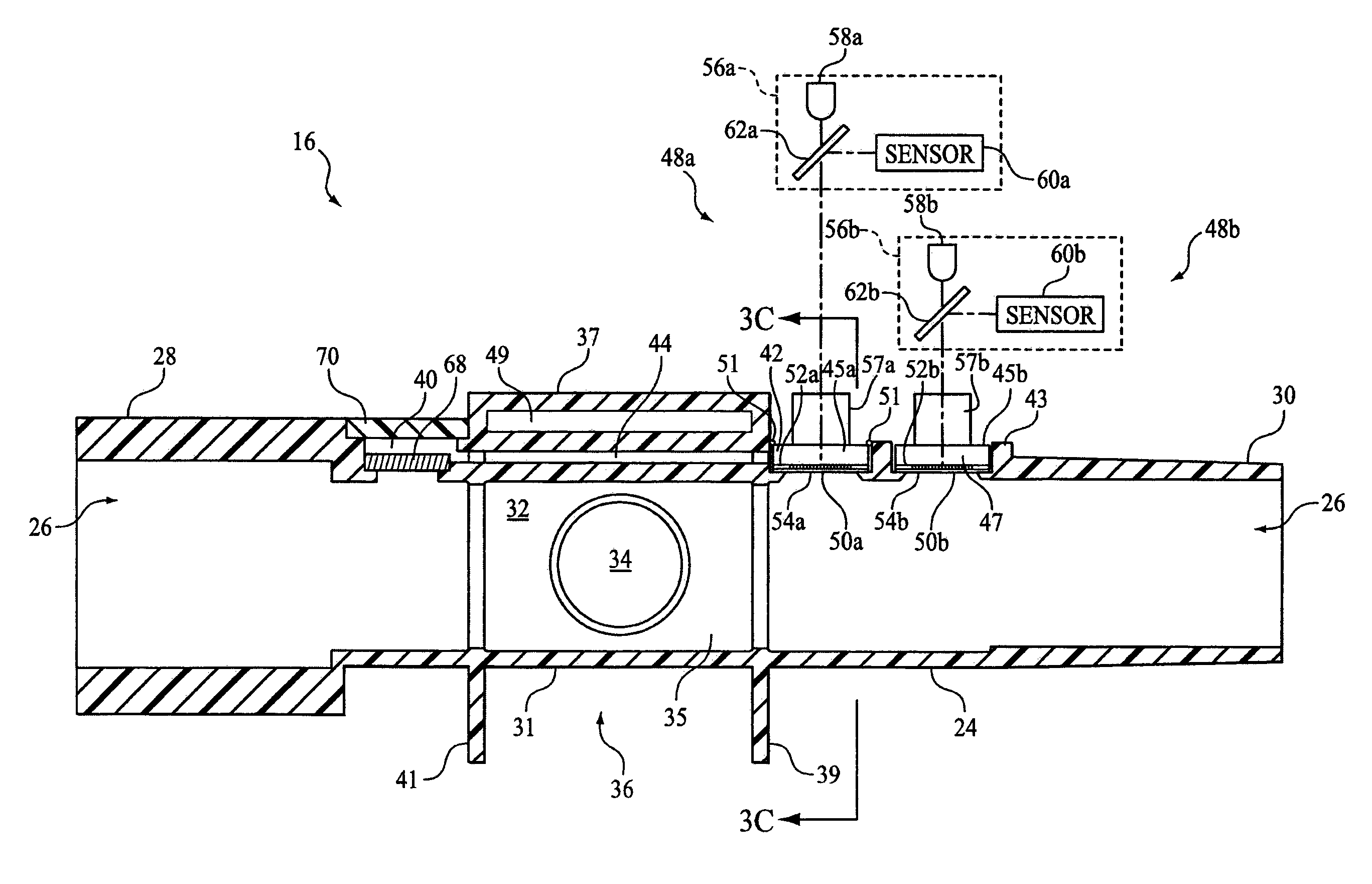
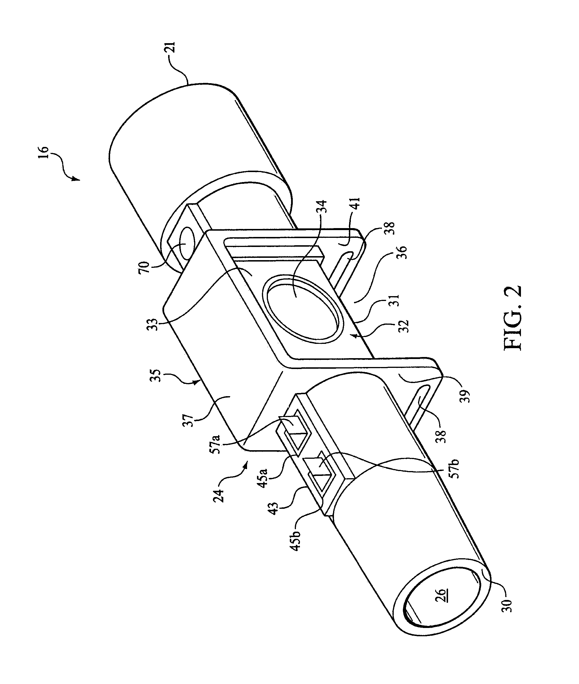
[0039]As is shown in FIG. 1, airway adaptor 16 is disposed along the length of respiratory circuit 10. Airway adaptor 16 includes one or more sensors ...


PUM


Abstract

An airway adapter that comprises a housing and a pressure transducer. The housing comprises a flow path having a first end and a second end, a first pressure port that communicates with the flow path, and a second pressure port that communicates with the flow path. The first pressure port is spaced apart from the second pressure port. The flow restriction is disposed in the flow path between the first and second pressure ports that creates a pressure differential therebetween. The pressure transducer generates a signal that reflects the differential pressure created by the flow restriction between the first and second pressure ports, wherein the pressure transducer comprises an optical interferometer.

Description

CROSS-REFERENCE TO RELATED APPLICATIONS[0001]This application claims priority under 35 U.S.C. § 119(e) from provisional U.S. patent application No. 60 / 808,312, filed May 25, 2006, the contents of which are incorporated herein by reference.BACKGROUND OF THE INVENTION[0002]1. Field of the Invention[0003]The invention relates to a method of manufacture of a interferometric sensor component and the implementation of an interferometer to detect a pressure differential in a gas flow path.[0004]2. Description of the Related Art[0005]Respiratory gas flow measurement during the administration of anesthesia, in intensive care environments, and in monitoring the physical condition of athletes and other individuals prior to and during the course of training programs and other medical tests provides valuable information for assessment of cardiopulmonary function and breathing circuit integrity. Many different technologies have been applied to create a flow meter that attempts to meet the demandi...

Claims


Application Information

Patent Timeline
Patent Type & Authority Patents(United States)
IPC IPC(8): G01B9/02
CPCA61M16/08G01B9/02G01F1/38G01F1/383G01F1/40G01L9/0077A61M2016/0027A61M2016/0036A61M2016/102A61M16/0858A61M16/0866G01B9/02023G01B2290/25
Inventor RUSSELL, JAMES T.
Owner RIC INVESTMENTS LLC
Why Eureka
Try Eureka