Image forming apparatus that prevents conspicuous unevenness in image density

a technology of image density and forming apparatus, which is applied in the direction of electrographic process apparatus, optics, instruments, etc., can solve the problems of uneven density caused by depressed and projecting sections, uneven density of density, so as to prevent uneven density from becoming conspicuous

Inactive Publication Date: 2009-06-30
SEIKO EPSON CORP
View PDF7 Cites 8 Cited by
  • Summary
  • Abstract
  • Description
  • Claims
  • Application Information

AI Technical Summary

Benefits of technology

[0013]The present invention has been made in view of the above issues. An object of the present invention is to achieve an image forming apparatus which can prevent unevenness in density from becoming conspicuous.

Problems solved by technology

When dot-like latent images are made visible as a developer image by the developer which is borne by the developer bearing roller having the groove portion, there are cases in which unevenness in density may occur periodically in the developer image (for example, unevenness in density which is caused because an amount of the developer borne by the groove portion is more than an amount of the developer borne by any other section than the groove portion).
However, if the depressed / projecting section is formed on the surface of the developer bearing roller, when dot-like latent images are made visible as a developer image, there are cases in which unevenness in density caused by the depressed and projecting section may occur periodically in the developer image (for example, unevenness in density which is caused because an amount of developer borne by a projecting portion is different from an amount of developer borne by a depressed portion).
Thus, unevenness in density occurring periodically is conspicuous, so that image quality may deteriorate.

Method used


Image

  • Image forming apparatus that prevents conspicuous unevenness in image density
  • Image forming apparatus that prevents conspicuous unevenness in image density
  • Image forming apparatus that prevents conspicuous unevenness in image density

Examples


first embodiment

Regarding Modified Example of First Embodiment

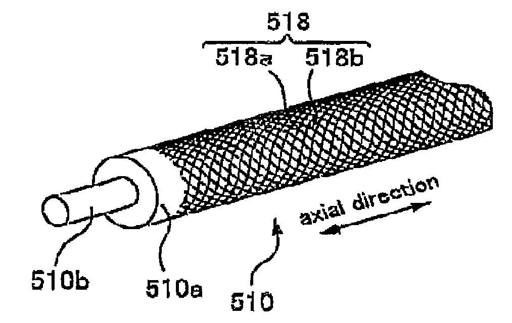
[0215]Next, with reference to FIGS. 18A through 18D, a modified example of the first embodiment is described. FIGS. 18A through 18D are front views of schematic diagrams of the developing roller 510; FIG. 18A shows the developing roller 510 of the black developing device 51, FIG. 18B shows the developing roller 510 of the magenta developing device 52, FIG. 18C shows the developing roller 510 of the cyan developing device 53, and FIG. 18D shows the developing roller 510 of the yellow developing device 54.

[0216]The section below mainly describes the positional relationship between the depressed portion 518 of the developing roller 510 and the divided-region rows of the screens. Accordingly, a structure of the printer 10 which is the same as the printer 10 according to the first embodiment is not described.

[0217]In the modified example, the first developer and the second developer can be any toner among toners of four colors, so yellow tone...

second embodiment

Regarding Positional Relationship between Indentation-Processed Section 512 and Divided Regions, of Printer 10 according to Second Embodiment

[0229]The photoconductor 20 bears dot-like latent images by the divided regions which are divided into lattices. A plurality of the divided regions exist in this embodiment, and are located in rows along the axial direction and the circumferential direction of the photoconductor 20.

[0230]The printer 10 according to this embodiment can form an image with a resolution of 200 dpi to 600 dpi; for example, it forms, with a resolution of 600 dpi, an image which does not occupy a wide area, such as characters and line drawings, and forms, with a resolution of 200 dpi, an image which occupies a wide area, such as photographs and illustrations. The printer 10 changes pitches of lattices which form divided regions, depending on the resolution. More specifically, the lattices which form divided regions can be formed having a plurality of types of pitches ...


PUM


Abstract

An image forming apparatus includes: an image bearing body that is rotatable about a central axis thereof, and that bears a dot-like latent image, on a surface of the image bearing body, in each of a plurality of divided regions that are arranged in rows along a direction that intersects an axial direction of the central axis at a predetermined intersection angle; and a developer bearing roller that is rotatable in order to make visible, as a developer image, the dot-like latent images borne by the image bearing body, using a developer borne on a surface of the developer bearing roller, the developer bearing roller opposing the image bearing body such that an axial direction of the developer bearing roller is parallel to the axial direction of the image bearing body, and that includes a helical groove portion on the surface of the developer bearing roller, the helical groove portion being inclined at a predetermined inclination angle with respect to the axial direction of the developer bearing roller and being formed having a uniform pitch in the axial direction, wherein a value that is a tangent of the inclination angle divided by a ratio of a moving speed of the surface of the developer bearing roller to a moving speed of the surface of the image bearing body is different from a tangent of the intersection angle.

Description

CROSS-REFERENCE TO RELATED APPLICATIONS[0001]The present application claims priority from Japanese Patent Applications No. 2006-8821 filed on Jan. 17, 2005 and No. 2006-8822, filed on Jan. 17, 2005, which are herein incorporated by reference.BACKGROUND[0002]1. Technical Field[0003]The present invention relates to image forming apparatuses which are for forming an image.[0004]2. Related Art[0005]Image forming apparatuses such as a laser beam printer have been well-known. Such image forming apparatuses are furnished with, for example, an image bearing body that is for bearing dot-like latent images, and a rotatable developer bearing roller that is for making visible as a developer image, using developer borne on a surface thereof, the dot-like latent images borne by the image bearing body. The image bearing body is rotatable about a central axis, and the developer bearing roller is opposes the image bearing body such that an axial direction thereof is parallel to an axial direction of...

Claims


Application Information

Patent Timeline
Patent Type & Authority Patents(United States)
IPC IPC(8): G03G15/08
CPCG03G15/0818
Inventor ARUGA, TOMOHIROYAMADA, YOICHISAKURAI, NOBORUFUKUMOTO, TAKATOMO
Owner SEIKO EPSON CORP
Why Eureka
Try Eureka