Low voltage amplifier having a class-AB control circuit

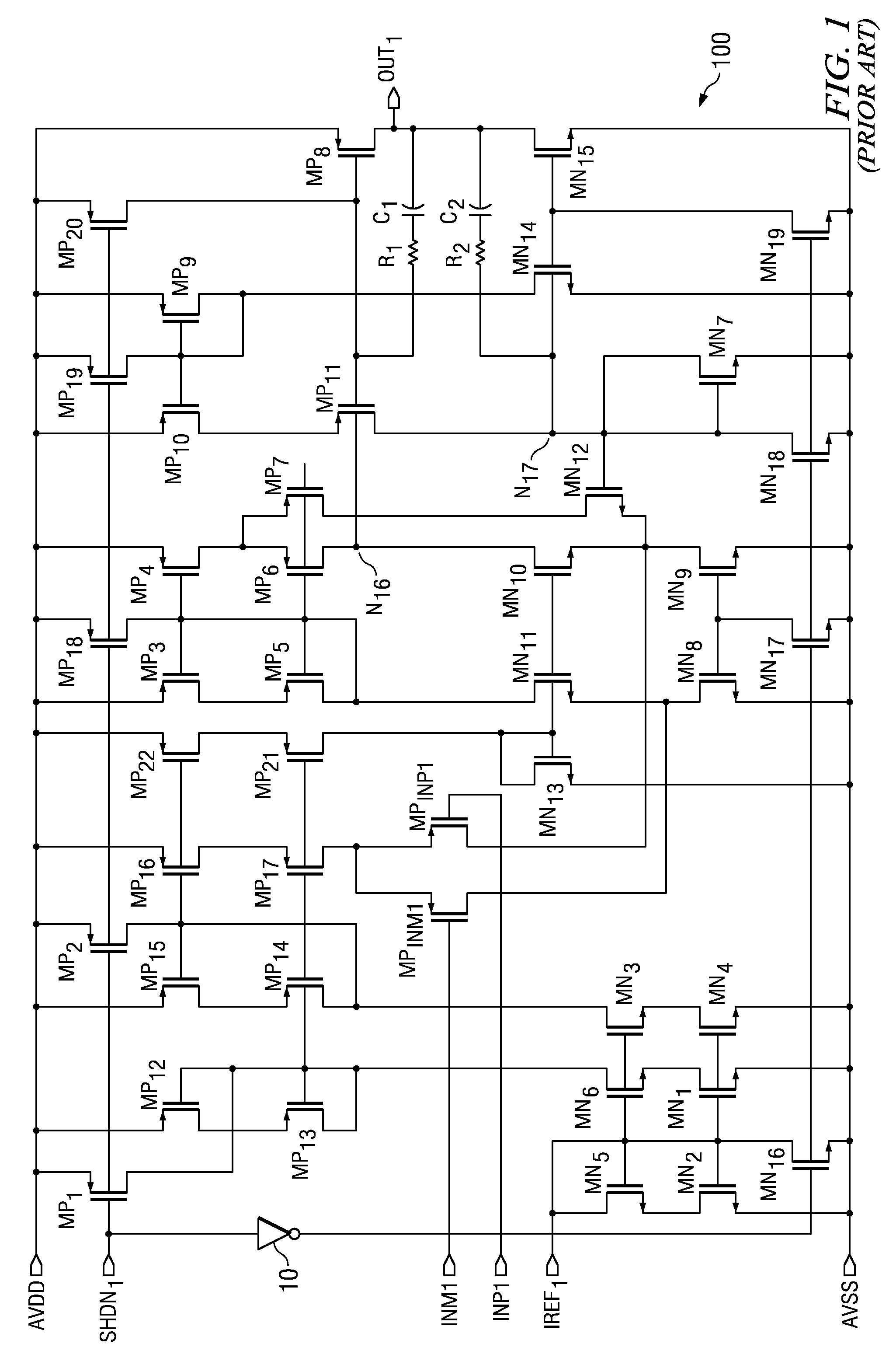
a control circuit and low-voltage amplifier technology, applied in the direction of dc-amplifiers with dc-coupled stages, differential amplifiers, amplifiers with semiconductor devices/discharge tubes, etc., can solve the problems of performance degradation, analog cells suffer from the reduction in size, and the class-ab control circuit within the amplifier shown in fig. 1 has a significant disadvantage, so as to reduce the effect of surge current and less dependent on process variation

Active Publication Date: 2009-07-07
TEXAS INSTR INC
View PDF2 Cites 31 Cited by
  • Summary
  • Abstract
  • Description
  • Claims
  • Application Information

AI Technical Summary

Benefits of technology

[0014]The advantages include but are not limited to a low voltage amplifier having a class-AB control circuit which generates minimal or no surge current when the output of the amplifier clips to ground or the negative rail. This amplifier is power supply independent. Moreover, the improved amplifier is less dependent on process variation. This solution provided by the improved amplifier completely eliminates the problems that arise as a result of surge current; whereas other solutions only diminish the effects of surge current.

Problems solved by technology

There is a benefit to the digital cells in that performance improves; however, analog cells suffer from the reduction in size since minimum size transistors cannot be used due to noise and offset requirements.
Low supply voltage requirements dictate a need for complex circuit solutions, which in some cases result in performance degradation.
The class-AB control circuit within the amplifier shown in FIG. 1, however, has a significant disadvantage.
Specifically, when the output of the amplifier clips to ground or the negative rail, a surge of current is pulled from the power supply.
The only limitation of current supplied by transistor MP9 is when the gate-to-source voltage Vgs of transistor MP9 is too large, wherein there is little voltage remaining if the gate-to-source voltage Vgs is subtracted from the supply voltage.
This poses a significant problem.
This approach, however, is not an adequate solution, in that it minimally limits the surge current; yet, a substantial amount of surge current exists.
Moreover, the minimized surge current remains power supply dependent.

Method used


Image

  • Low voltage amplifier having a class-AB control circuit
  • Low voltage amplifier having a class-AB control circuit
  • Low voltage amplifier having a class-AB control circuit

Examples


Embodiment Construction

[0023]One or more exemplary implementations of the present invention will now be described with reference to the attached drawings, wherein like reference numerals are used to refer to like elements throughout. The various aspects of the invention are illustrated below in a low voltage amplifier having an input stage, a summing circuit, a class-AB control circuit, and an output stage, although the invention and the appended claims are not limited to the illustrated examples.

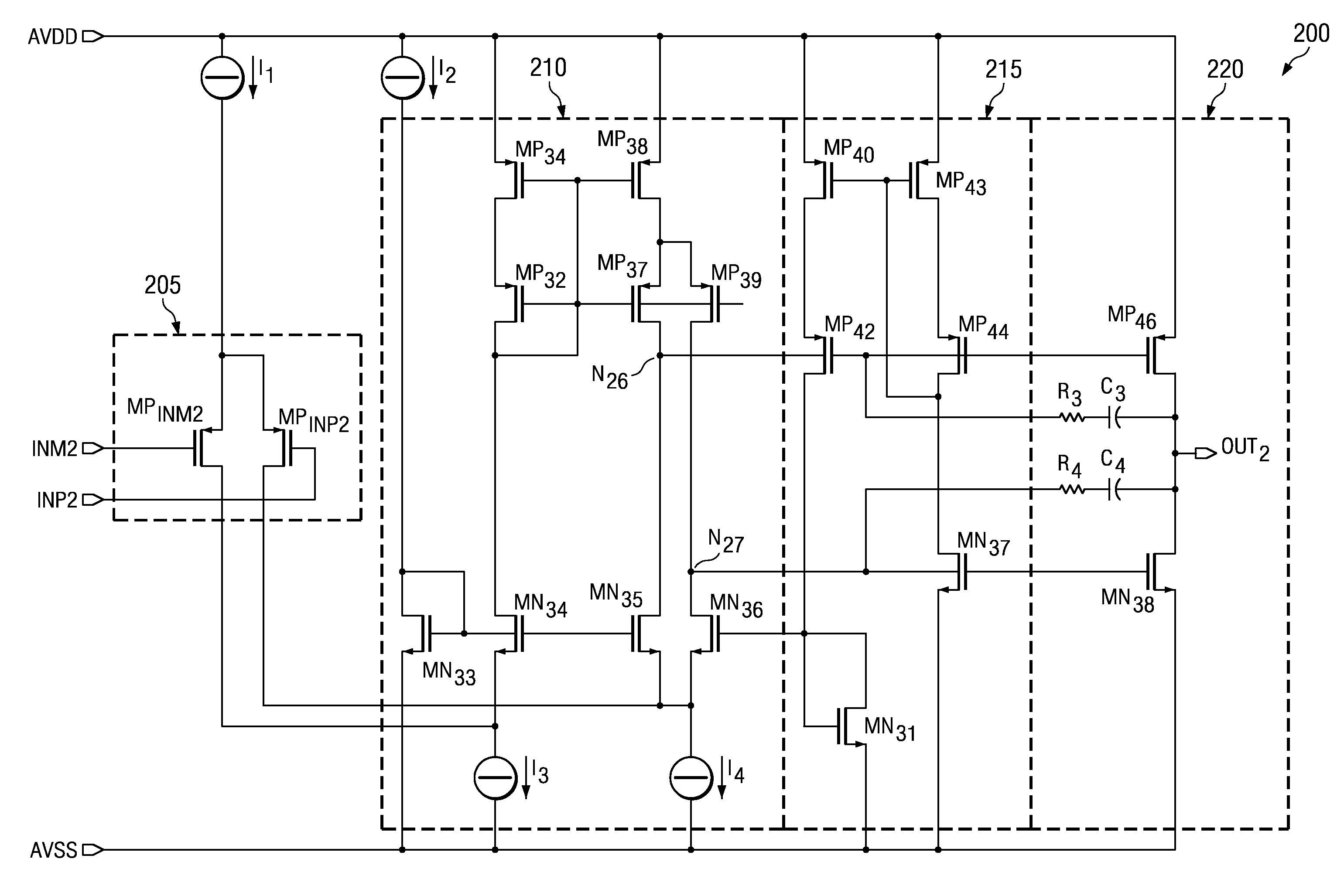
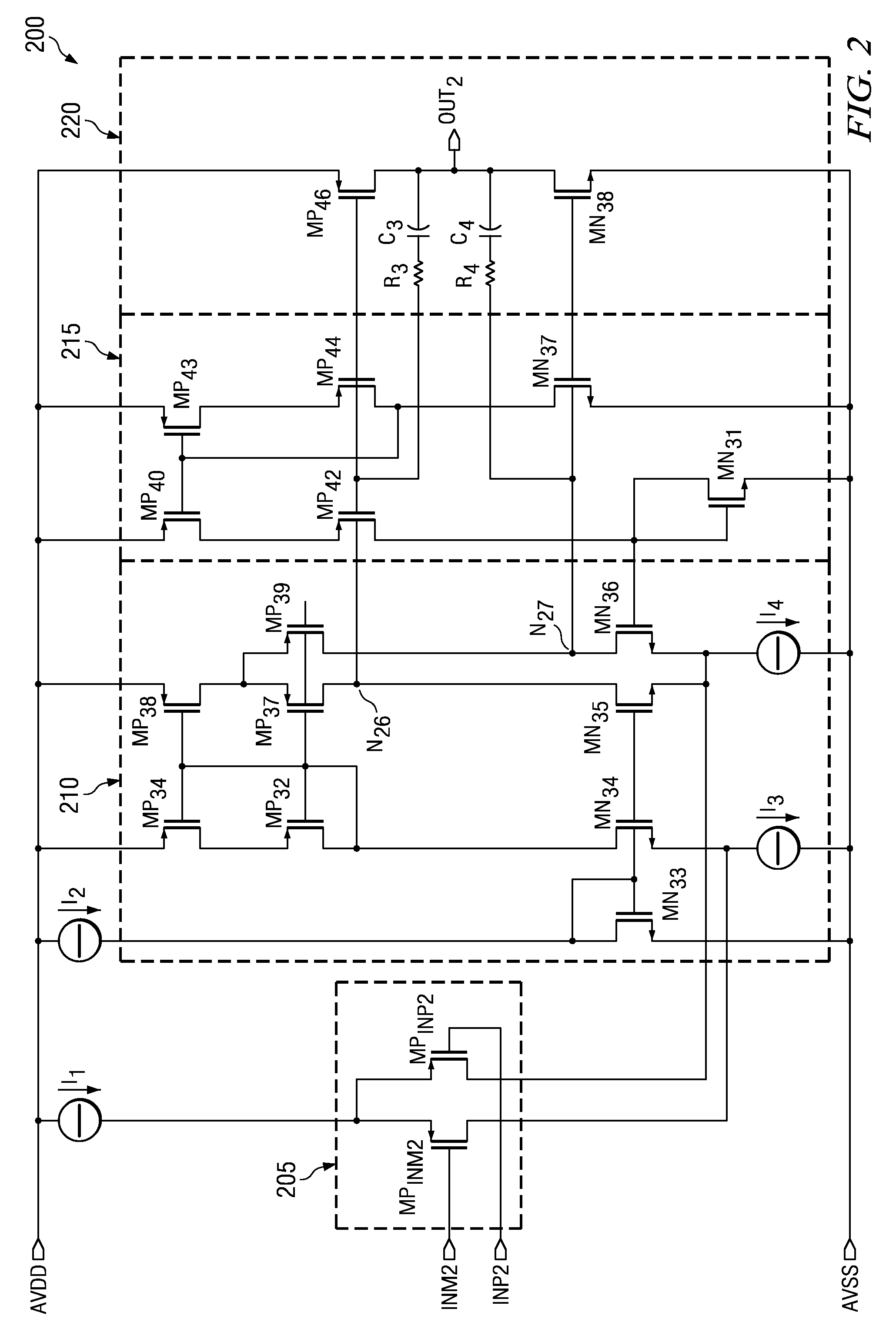
[0024]One embodiment of the low voltage amplifier having a class-AB control circuit configured as a folded cascode amplifier which generates minimal or no surge current when the output of the amplifier clips to ground or the negative rail is illustrated in FIG. 2. As shown, an input stage 205 connects to receive a positive and a negative input, INP2 and INM2, to receive a differential input signal. A first and second current source, I1 and I2, connect to the input stage 205 and the summing circuit 210, respective...


PUM


Abstract

A low voltage amplifier having a class-AB control circuit which generates minimal or no surge current when the output of the amplifier clips to ground or the negative rail. The amplifier includes an input stage, a summing circuit, a class-AB control circuit and an output stage. The input stage connects to a first current source and couples to receive a pair of differential input signals to generate intermediate signals that are summed together using the summing circuit. A second current source supplies the summing circuit with current. The class-AB control circuit receives the summed signals from the summing circuit to provide control for the output stage which generates the amplifier result at the output of the amplifier which delivers current to drive an external load. Specifically, the class-AB control circuit is improved by the addition of a PMOS device connected in such a way to cut off the DC current path that is generated during the output stage clipping condition by a diode connected PMOS device and a NMOS sensing device both located near the output of the class-AB control circuit. Thereby, the additional PMOS device minimizes the surge current generated by the NMOS sensing device when the output of the amplifier clips to ground or the negative rail.

Description

[0001]This application claims priority under 35 U.S.C. § 119(e) of provisional application Ser. No. 60 / 586,013 filed Jul. 7, 2004.FIELD OF THE INVENTION[0002]The present invention relates to the field of differential amplifiers and operational amplifiers and more particularly to an amplifier of this kind fabricated in integrated circuit technology having a rail-to-rail common mode range at the amplifier output.BACKGROUND OF THE INVENTION[0003]With the reduction of feature size in complementary metal oxide semiconductor (CMOS) processes, supply voltage requirements decrease. This higher integration density provides that each digital and analog cell in a mixed signal very-large-scale-integration (VLSI) circuit consumes less power. There is a benefit to the digital cells in that performance improves; however, analog cells suffer from the reduction in size since minimum size transistors cannot be used due to noise and offset requirements. Low supply voltage requirements dictate a need f...

Claims


Application Information

Patent Timeline
Patent Type & Authority Patents(United States)
IPC IPC(8): H03F3/26
CPCH03F1/02H03F3/3022H03F3/45475H03F3/45183H03F2200/513H03F2200/471
Inventor PEREZ, RAUL A.
Owner TEXAS INSTR INC
Why Eureka
Try Eureka