Patient monitor pressure pad with effective date warning alarm

a technology of effective date and warning alarm, which is applied in the field of pressure pads, can solve the problems of unreliable monitoring system of patient monitoring pressure pads and limited time during which their operation is entirely reliable, and achieve the effect of preventing use and preventing unnecessary accidents

Active Publication Date: 2009-07-07
RONDISH
View PDF12 Cites 14 Cited by
  • Summary
  • Abstract
  • Description
  • Claims
  • Application Information

AI Technical Summary

Benefits of technology

[0013]The present invention is a patient monitor pressure pad for use in nursing homes, residential care facilities, hospitals, and other establishments that employ means to monitor the whereabouts of facility patients or residents. The pressure pad improves on prior art devices by providing a internal time sensor and alarm circuit that produces an audible or visible alarm output to alert facility care staff that the effective life of the pressure pad is nearing its end. It thus provides means to prevent use beyond the useful life of the pad and therefore to prevent needless accidents caused by unaccounted for patients or residents.
[0015]It is another object of the present invention to provide a new and improved patient monitor pressure pad that provides a conspicuous, perceptible signal that the useful life of the pressure pad is near its end.

Problems solved by technology

Patient monitoring pressure pads have a limited time during which their operation is entirely reliable.
This system of monitoring the patient monitoring pad is unreliable and calls for specific staff action to remember to initiate, and then initiate, an affirmative act to prevent an important care facility device from becoming ineffective.

Method used


Image

  • Patient monitor pressure pad with effective date warning alarm
  • Patient monitor pressure pad with effective date warning alarm
  • Patient monitor pressure pad with effective date warning alarm

Examples


embodiment 200

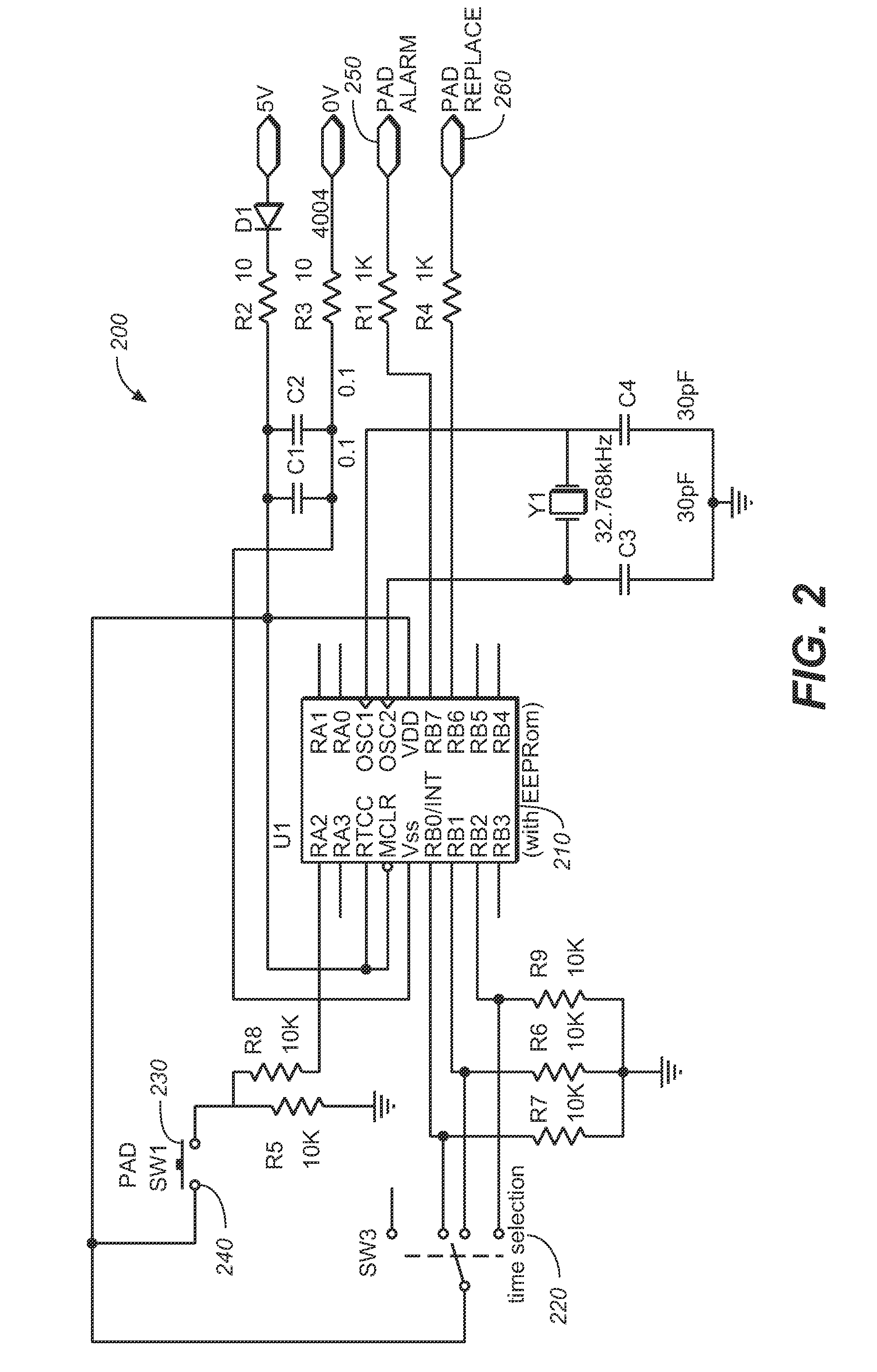
[0028]FIG. 2 shows a second preferred embodiment 200 of a circuit employed in the present invention. In this embodiment, in addition to a microprocessor 210 (preferably with EEPROM) that performs the timing operation on a circuit and appropriately updates memory, the circuit also includes a time selection switch 220 (such as a ganged wafer switch) which allows the user to select among different periods of time that must elapse before an alarm is activated. Once again, when the pad 230 is used, switch 240 activates the circuit, and after the pre-determined time has passed, a perceptible alarm 250 is activated via the alarm circuit, which also issues a “pad replace” instruction output 260.

embodiment 300

[0029]FIG. 3 shows a battery powered embodiment 300 of a circuit for the present invention, which also employs a microprocessor 310, but includes a battery 320 to power the circuit when electrical switch 330 is triggered by use of the pad 340. This circuit resembles the circuit shown in FIG. 2, but it can be employed as an aftermarket add-on to a pressure pad purchased separately in the market place. It will go into the alarm state when the predetermined time runs out.

[0030]FIG. 4 is yet another battery powered circuit 400 designed to emit an alarm 410 when the battery 420 runs low, rather than after use of the pad 430. The circuit must be manually turned on via the pad enable switch 440 to enable alarm operation and turn off with the same switch to conserve battery power.

[0031]Each of the circuits shown in FIGS. 3 and 4 will work with numerous patient pressure pad monitors and will go into the alarm condition only when a patient is lying on a bed. Those responsible for replacing wo...

embodiment 500

[0032]FIG. 5 shows a fifth preferred embodiment 500 of a circuit that may be used in the present invention. This circuit employs a battery 510 in conjunction with a dedicated “smart” monitor having a manually operable pad enable switch 520 and provides a dedicated “change pad” alert 530. Pads employing the circuits shown in each of FIGS. 4 and 5 must be switched off when not in use to conserve and extend battery life.


PUM


Abstract

A patient monitor pressure pad having a time sensor and alarm circuit that produces an audible or visible alarm output to alert facility care staff that the effective life of the pressure pad is nearing its end.

Description

CROSS REFERENCES TO RELATED APPLICATIONS[0001]The present application claims the benefit of U.S. Provisional Patent Application Ser. No. 60 / 696,001, filed Jul. 1, 2005 (Jul. 1, 2005).STATEMENT REGARDING FEDERALLY SPONSORED RESEARCH OR DEVELOPMENT[0002]Not applicable.THE NAMES OR PARTIES TO A JOINT RESEARCH AGREEMENT[0003]Not applicable.INCORPORATION-BY-REFERENCE OF MATERIAL SUBMITTED ON A COMPACT DISC[0004]Not applicable.BACKGROUND OF THE INVENTION[0005]1. Field of the Invention[0006]The present invention relates generally to apparatus for monitoring patient movement, and more particularly to pressure pad for use on a chair, bed, or other surface typically occupied by a patient or resident and having an operably connected alarm system for alerting staff when the patient or resident has moved outside a defined area. Even more particularly, the present invention relates to a patient monitoring pressure pad having a time sensor and alarm that alerts hospital or residential care staff t...

Claims


Application Information

Patent Timeline
Patent Type & Authority Patents(United States)
IPC IPC(8): G08B23/00G08B1/00G08B21/00
CPCA61B5/1115A61B2560/028A61B5/6892A61G2203/34A61B5/7405
Inventor LONG, TIMOTHY
Owner RONDISH
Why Eureka
Try Eureka