Core catcher cooling

a core catcher and cooling technology, applied in the field of nuclear reactors, can solve the problem that the method of long-term stabilization by cooling the molten core debris does not include long-term stabilization

Inactive Publication Date: 2009-07-07
GENERAL ELECTRIC CO
View PDF20 Cites 45 Cited by
  • Summary
  • Abstract
  • Description
  • Claims
  • Application Information

AI Technical Summary

Problems solved by technology

However, some methods do not include long-term

Method used


Image

  • Core catcher cooling
  • Core catcher cooling
  • Core catcher cooling

Examples


Embodiment Construction

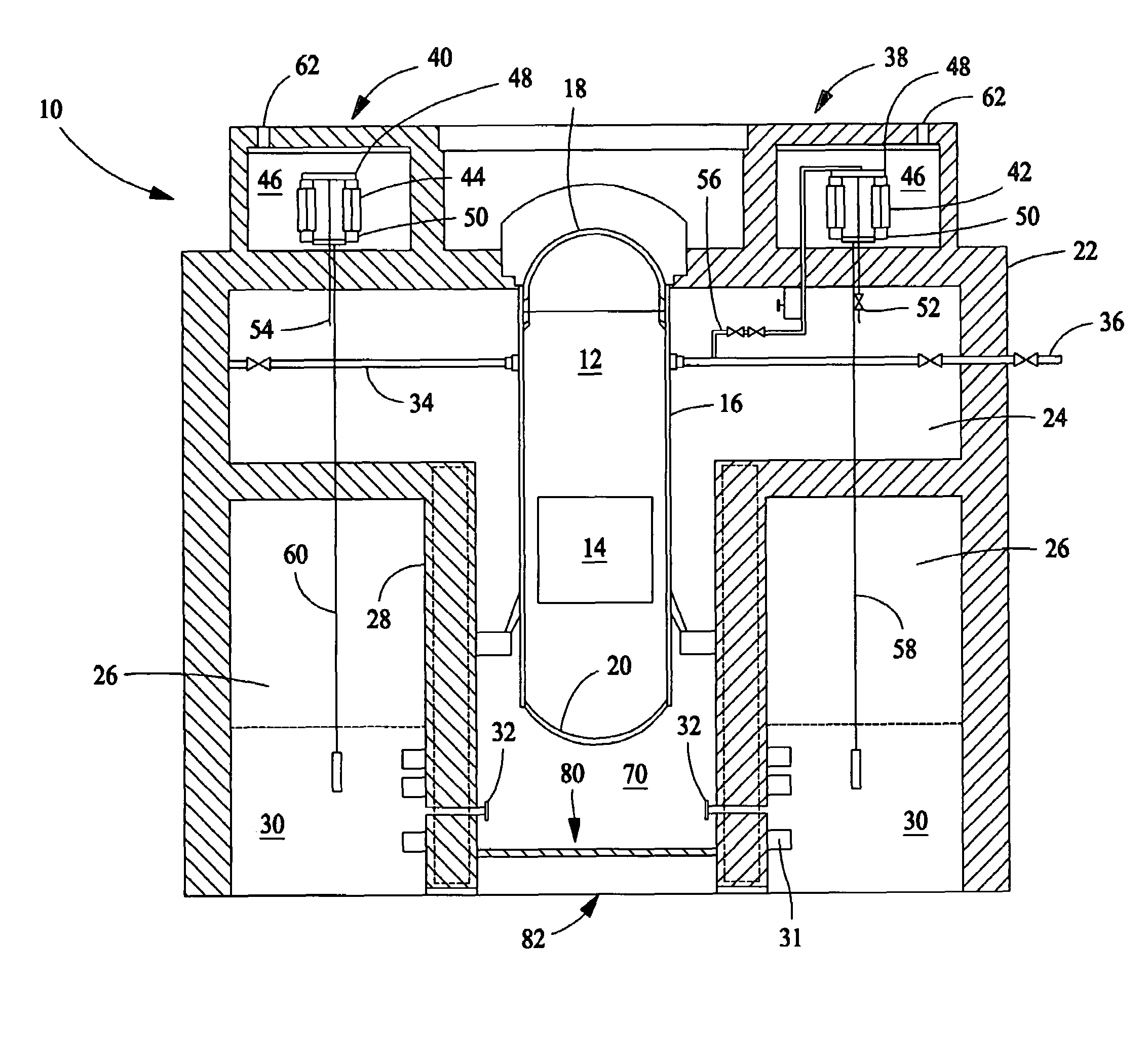
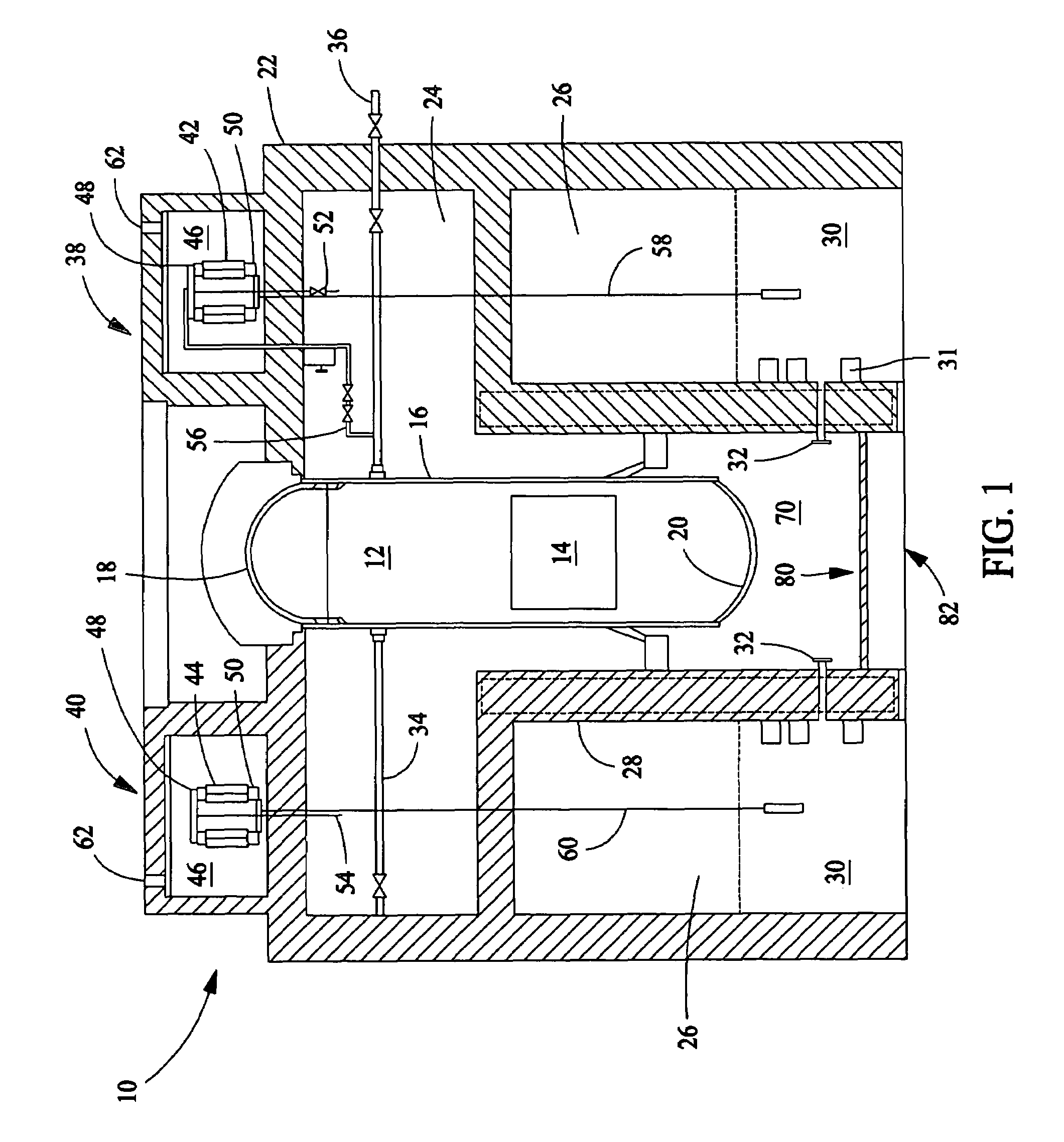
[0010]FIG. 1 is a schematic depiction of a nuclear reactor system 10 in accordance with one embodiment of the present invention. Nuclear reactor system 10 includes a cylindrical reactor pressure vessel 12 (RPV) which encloses a reactor core 14. RPV 12 includes a cylindrical wall 16 sealed at one end by a top head 18 and at the other end by a bottom head 20. RPV 12 is housed in a primary containment vessel 22 (PCV). The inside surface of the primary containment vessel 22 is lined with a steel liner. Primary containment vessel 22 includes a drywell 24 and a wetwell 26. In one embodiment, drywell 24 is a concrete cylinder with a domed top, and wetwell 26 is an annular chamber formed by a RPV pedestal or wall 28 and primary containment vessel 22. A suppression pool of water 30 is located in wetwell 26, and RPV 12 is located in drywell 24. Connection between drywell 24 and wetwell 26 is provided by the drywell / wetwell vent system embedded within wall 28. During a severe accident, additio...


PUM


Abstract

An assembly includes a base grid configured to be disposed below a pressure vessel and spaced vertically above a floor of a containment vessel to define a sump therebetween. The assembly further includes an annular wall extending vertically upwards from the floor and laterally bounding the base grid and the sump. The wall separates the sump from a suppression pool, an inlet passage extending through the wall and providing flow communication between the sump and the suppression pool, and an outlet passage extending through the wall and providing flow communication between the sump and the suppression pool.

Description

BACKGROUND OF THE INVENTION[0001]This invention relates generally to nuclear reactors and more particularly to a heat removal system in a containment.[0002]One known boiling water nuclear reactor includes a reactor pressure vessel (RPV) positioned in a drywell, or containment, suppression pool (SP) and a passive containment cooling system (PCCS). The RPV contains a core, and the containment is designed to withstand design pressure defined by a loss of coolant accident (LOCA) and other loads associated with plant operation. The PCCS is configured to limit the containment pressure below the design value and to keep the RPV core substantially cool during a postulated loss of coolant accident.[0003]Typically the bottom floor of the containment vessel is part of the basemat of the reactor building. The basemat, in certain situations, rests on bedrock and typically supports the reactor building, containment vessel wall, suppression pool and reactor pedestal that supports the RPV including...

Claims


Application Information

Patent Timeline
IPC IPC(8): G21C9/00G21C9/016
CPCG21C9/016Y02E30/40Y02E30/30
Inventor GAMBLE, ROBERT EDWARDABUROMIA, MOMTAZ MAHDIGOU, PERNG-FEI
Owner GENERAL ELECTRIC CO
Why Eureka
Try Eureka