
Anisotropic texture filtering optimization

a texture filtering and optimization technology, applied in the field of computer graphics, can solve the problems of reducing the performance attributable to including the additional bilerps, reducing and reducing the performance of the additional bilerps. the effect of increasing the image quality, reducing performance, and optimizing the number of bilinear samples

Active Publication Date: 2009-07-07
NVIDIA CORP
View PDF17 Cites 9 Cited by
  • Summary
  • Abstract
  • Description
  • Claims
  • Application Information

AI Technical Summary

Benefits of technology

[0017]One advantage of the disclosed method is that it optimizes the number of bilinear samples used in an anisotropic texture filter when computing a texture value for a pixel. By recognizing the tradeoff between image quality and performance, the disclosed method uses fewer bilinear interpolations when the corresponding increase in performance outweighs the corresponding decrease in image quality. Conversely, the disclosed method uses more bilinear interpolations when the corresponding increase in image quality outweighs the corresponding decrease in performance.

Problems solved by technology

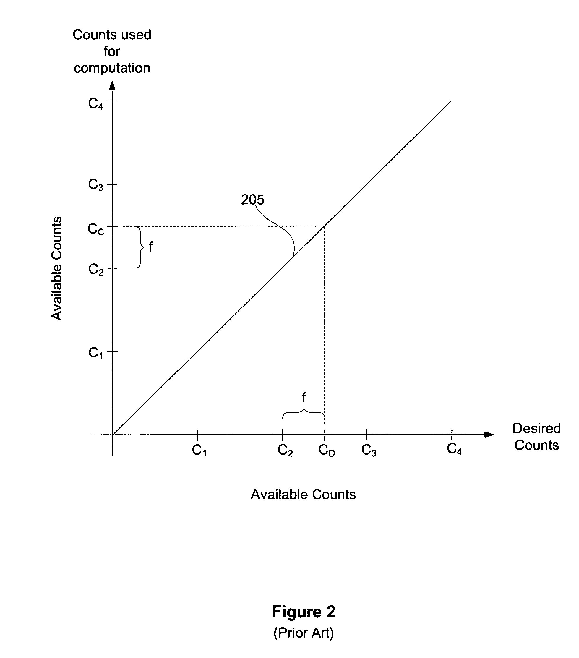
On drawback of calculating the texture value for the pixel footprint in this manner is that, when the fractional distance (f) is small, the texture values for the additional bilerps are heavily discounted and, therefore, may have relatively little influence on the final texture value.
In effect, substantial computational effort may be wasted when the fractional portion (f) is small because the additional bilerps do not contribute much to overall image quality.
In other words, when the texture values for the additional bilerps are heavily discounted, the decrease in performance attributable to including the additional bilerps when computing the final texture value may outweigh the marginal increase in overall image quality attributable to the additional bilerps.

Method used


Image

  • Anisotropic texture filtering optimization
  • Anisotropic texture filtering optimization
  • Anisotropic texture filtering optimization

Examples


Embodiment Construction

[0027]FIG. 4A illustrates a graph of a function 405 used to compute a modified bilerp count, according to one embodiment of the present invention. Again, both axes of the graph include the bilerp counts available within a particular graphics system (C1, C2, C3 and C4). The desired bilerp count (CD) is shown along the x-axis, and a modified bilerp count (CM) is shown along the y-axis. Function 405 sets forth how the number of bilerps used to compute the texture value for a pixel is optimized by clamping the modified bilerp count to an integer value, corresponding to an available bilerp count, when the desired bilerp count falls within certain ranges. More specifically, the modified fractional distance (fm) associated with the modified bilerp count (CM) is clamped to zero when the fractional distance (f) associated with the desired bilerp count (CD) falls within specific, defined ranges. Once outside each of these ranges, the modified fractional distance (fm) transitions from zero to ...


PUM


Abstract

A method for optimizing the number of bilinear samples includes the steps of computing a desired bilerp count for a pixel footprint in a mipmap, where a fractional distance represents the distance between the desired bilerp count and a first available bilerp count relative to the distance between a second available bilerp count and the first available bilerp count, determining a modified bilerp count based on the desired bilerp count, and computing a modified fractional distance based on the modified bilerp count, where the modified fractional distance is zero if the fractional distance is between zero and a first-non-zero value, but is between zero and one if the fractional distance is within a transition band. Texture values for the bilerps in the first available count and one or more additional bilerps are average to generate a pixel texture value, where the modified fractional distance determines the weights applied.

Description

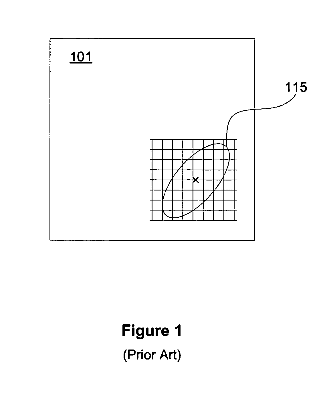
BACKGROUND OF THE INVENTION[0001]1. Field of the Invention[0002]Embodiments of the present invention relate generally to computer graphics and more specifically to anisotropic optimization for texture filtering.[0003]2. Description of the Related Art[0004]Conventional graphics processors read and filter texture maps to add texture detail and increased realism to rendered objects. This process, commonly referred to as “texture filtering,” may be simplified by pre-filtering a given texture map to various resolution levels, where each pre-filtered resolution level forms a “mipmap.” The resolution level associated with a given mipmap is commonly referred to as a “level of detail” (LOD).[0005]When texturing a pixel, the pixel is first mapped from screen space to texture space. In a case where mipmaps are used, the pixel is mapped to the appropriate mipmap. The region in texture space corresponding to a pixel is commonly called the pixel footprint. While a pixel is usually approximated by...

Claims


Application Information

Patent Timeline
Patent Type & Authority Patents(United States)
IPC IPC(8): G06K9/00G09G5/00
CPCG06T15/04G09G5/28G09G2340/0457G09G5/363
Inventor TOKSVIG, MICHAEL J. M.NEWHALL, JR., WILLIAM P.
Owner NVIDIA CORP
Learn More