Image dynamic range control for visual display

a dynamic range and visual display technology, applied in the field of image dynamic range control for visual display, can solve the problems of inability to reliably represent the relative thermal differences between these three areas along with the minute thermal differences within each of these areas, and the differences in perceived intensity with varying input intensity, etc., to achieve stable global intensity levels, low intensity contrast, and high spatial frequency details

Active Publication Date: 2009-07-07
PECO
View PDF10 Cites 9 Cited by
  • Summary
  • Abstract
  • Description
  • Claims
  • Application Information

AI Technical Summary

Benefits of technology

[0007]The preferred embodiments disclosed achieve mapping of high dynamic range image data to render on a lower dynamic range display device a corresponding image characterized by stable global intensity levels and visually perceptible local area detail. The high dynamic range image data include representations of relatively low intensity contrast, high spatial frequency details and relatively low spatial frequency intensities. Data derived from the high dynamic range image data are applied to a nonlinear intensity transform. The nonlinear intensity transform preserves or enhances the low intensity contrast, high spatial frequency details and maintains a visually perceptible representation of the relatively low spatial frequency inte...

Problems solved by technology

The output of sensors with a high dynamic range can be difficult to render on typical imaging displays.
The need to render large differences in intensity and the need to achieve sufficient contrast in areas of relatively uniform intensity compete with each other, given the limited dynamic range of available display devices.
In this case, reliably representing the relative thermal differences among these three areas along with minute thermal differences within each of these areas would be impos...

Method used


Image

  • Image dynamic range control for visual display
  • Image dynamic range control for visual display
  • Image dynamic range control for visual display

Examples


Embodiment Construction

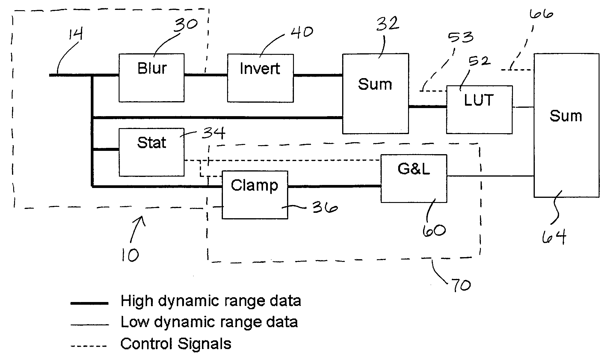
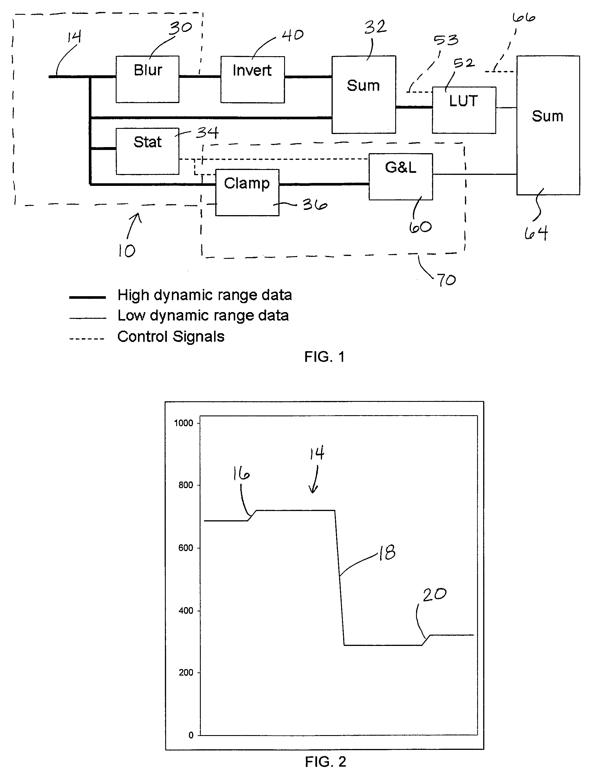
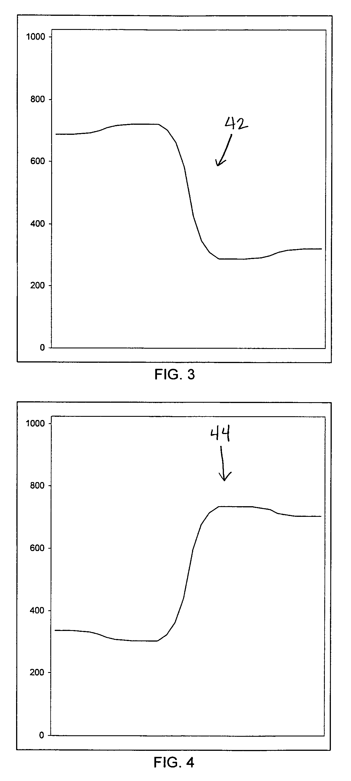
[0014]The preferred embodiments include a number of modular processing units existing as computer algorithms implemented in a general processing unit or as hardware constructs in, for instance, a field programmable gate array (FPGA), as arranged in a system 10 shown in FIG. 1. System 10 receives a high dynamic range image data waveform produced by a high dynamic range imaging device, such as a thermal infrared camera (not shown). FIG. 2 shows an arbitrary high dynamic range (HDR) image data waveform 14 representing, for example, a 10-bit input signal. HDR waveform 14 has three discontinuities 16, 18, and 20. FIGS. 3, 4, 5, 6, 7, 8, and 9 show the waveforms produced at the outputs of their associated processing units of system 10 in response to application of HDR waveform 14. Each of these drawing figures depicts along the Y-axis the full extent of the dynamic range of intensity and represents along the X-axis a series of hypothetical pixels along a single line of the image data repr...


PUM


Abstract

Preferred embodiments of an image display system achieve mapping of high dynamic range image data to render on a lower dynamic range display device a corresponding image characterized by stable global intensity levels and visually perceptible local area detail. The high dynamic range image data include representations of relatively low intensity contrast, high spatial frequency details and relatively low spatial frequency intensities. Data derived from the high dynamic range image data are applied to a nonlinear intensity transform. The nonlinear intensity transform preserves or enhances the low intensity contrast, high spatial frequency details and maintains a visually perceptible representation of the relatively low spatial frequency intensities to thereby provide visually perceptible local area detail. An exemplary embodiment derives high dynamic range image data from a thermal infrared camera for use with aircraft.

Description

TECHNICAL FIELD[0001]This disclosure describes a system and method by which arbitrary images produced by a high dynamic range camera are displayed on a dynamic range-limited display device. The system and method process image data in such a way as to maintain or enhance local contrast while limiting overall image dynamic range.BACKGROUND INFORMATION[0002]The output of sensors with a high dynamic range can be difficult to render on typical imaging displays. The need to render large differences in intensity and the need to achieve sufficient contrast in areas of relatively uniform intensity compete with each other, given the limited dynamic range of available display devices. An example is a thermal infrared image of a warm airport runway that includes areas of clear sky. The runway will be hot relative to non-runway ground areas, and very hot relative to the sky areas. In this case, reliably representing the relative thermal differences among these three areas along with minute therm...

Claims


Application Information

Patent Timeline
IPC IPC(8): G06K9/40
CPCG06T5/009H04N5/208G06T5/40G06T2207/20208G06T5/00H04N5/14H04N5/20
Inventor ZURO, GREGORY
Owner PECO
Why Eureka
Try Eureka