Connectivity controlled wire routing

a wire routing and wire technology, applied in the direction of insulated conductors, cables, instruments, etc., can solve the problems of complex wiring system, cumbersome and time-consuming tasks, and expense associated with creating mock-ups, so as to simplify the routing system and reduce the number of geometric entities

Active Publication Date: 2009-07-07
DASSAULT SYST SOLIDWORKS CORP
View PDF5 Cites 41 Cited by
  • Summary
  • Abstract
  • Description
  • Claims
  • Application Information

AI Technical Summary

Benefits of technology

[0011]Embodiments may include applying another filter to the connections for further visual simplification of the routing system. Moreover, the other filter can use the supplemental data and ca...

Problems solved by technology

When modeling electromechanical parts, a design engineer may design a wiring system that is quite complex with thousands of required connections between hundreds of different connectors and items of equipment.
Such tools replace the cumbersome and time-consuming task of, and save the expense related to creating mock-ups.
Disadva...

Method used


Image

  • Connectivity controlled wire routing
  • Connectivity controlled wire routing
  • Connectivity controlled wire routing

Examples


Embodiment Construction

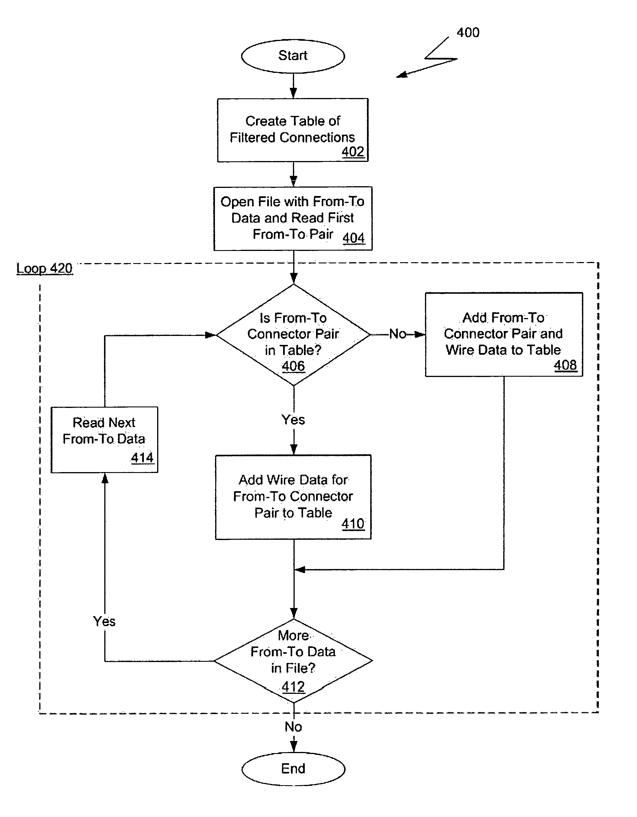
[0029]The present invention provides advanced modeling capabilities for the design of routing systems. Such modeling capabilities include the visualization and creation of necessary routes. The present invention facilitates the design of complex routing systems by electrical design engineers who may be inexperienced in 3D CAD modeling, reduces the number of errors in a routing system by deriving all data from a from-to list of connections, and aids in the discovery of the most efficient routing thereby reducing costs and design time, and minimizing the amount of re-work necessary and the amount of wire stress.

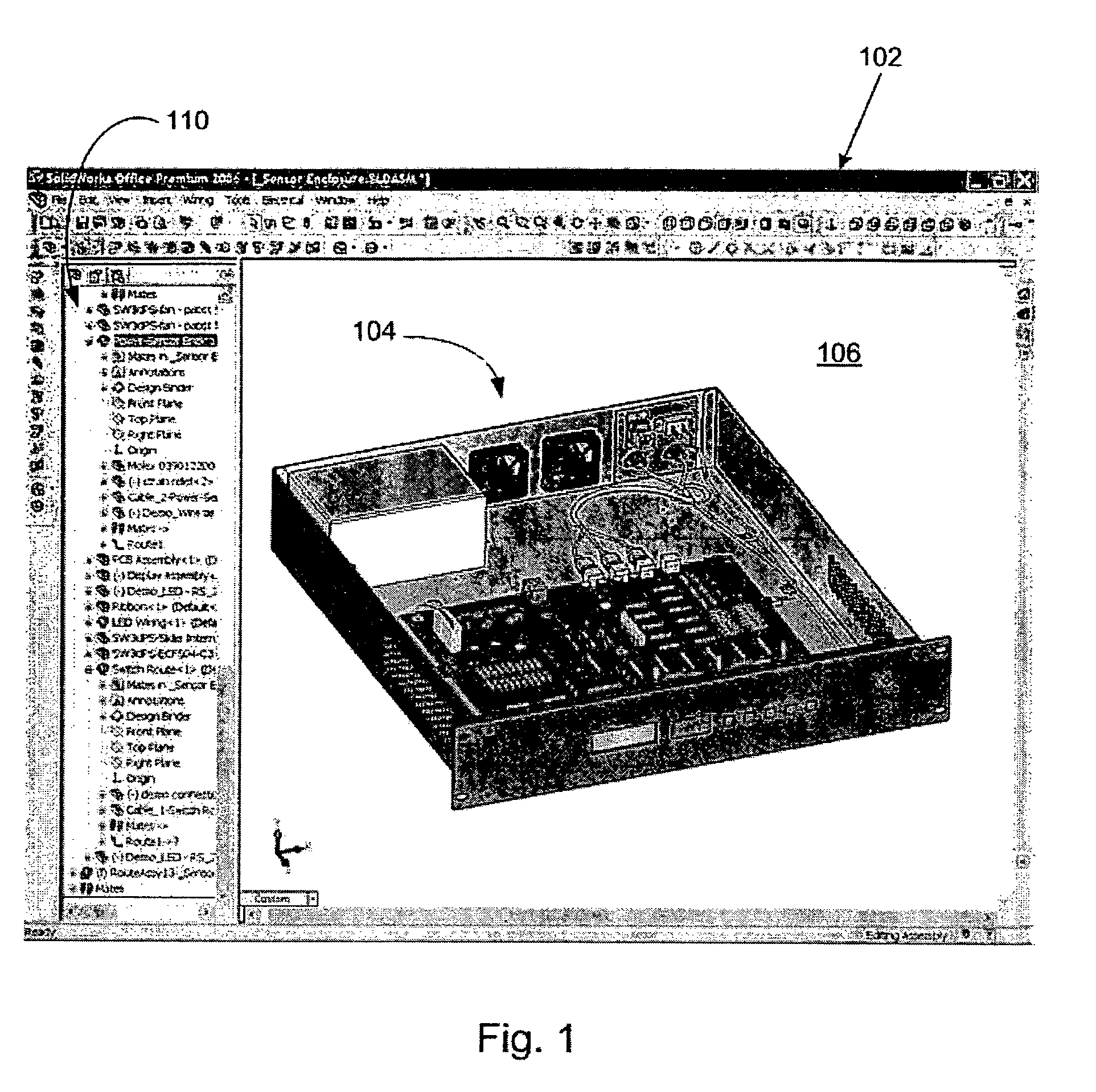
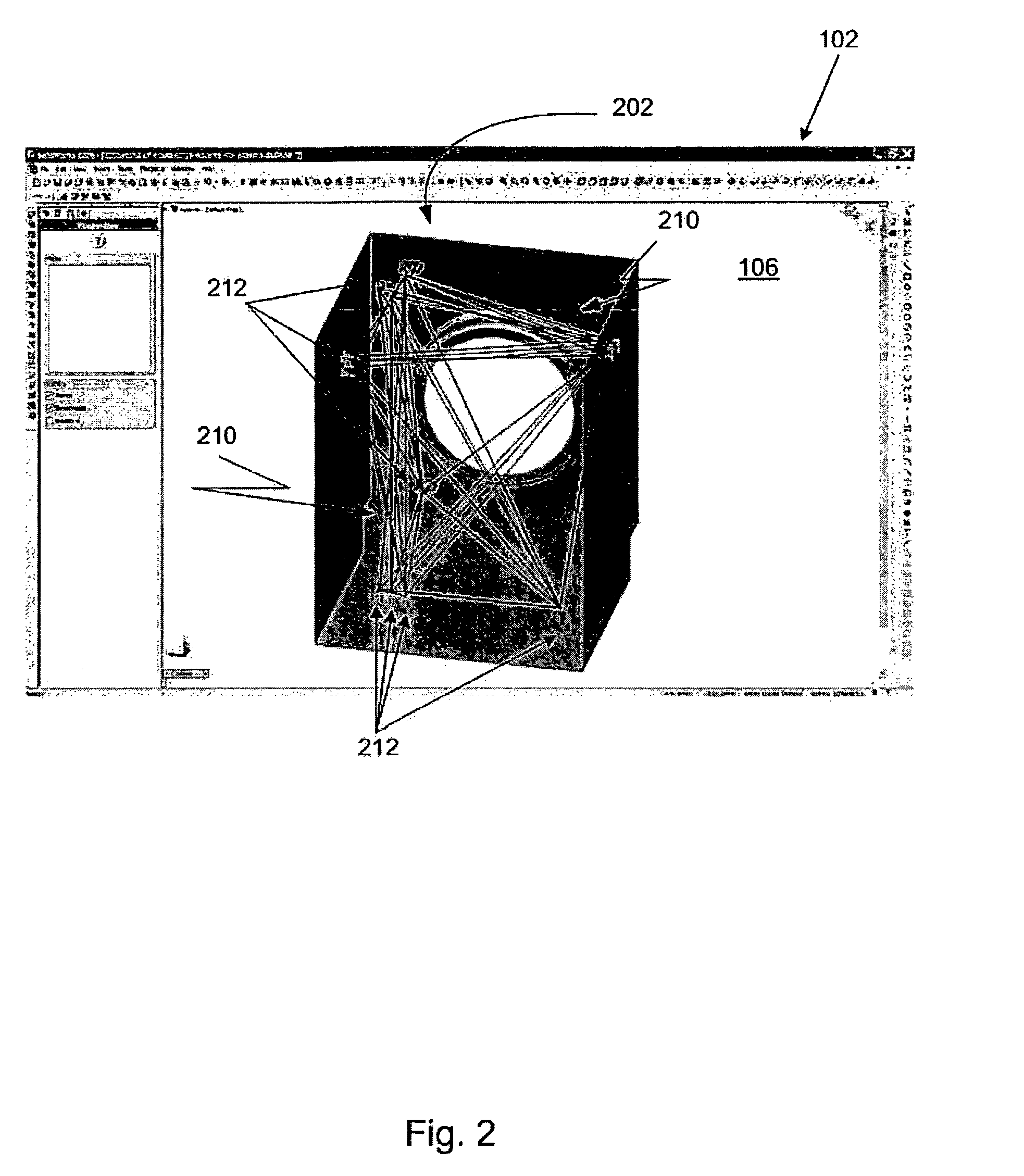
[0030]The present invention assists in creating a virtual mockup and enables engineers to easily and quickly visualize wiring and cabling systems. Using the present invention, a design engineer can create harness bundles and route elements of the harness through a 3D model. Moreover, the present invention can automatically convert individual wires or cables into a route, join a...


PUM


Abstract

Generating a routing system for a three-dimensional model of a real-world object includes specifying a set of connections, applying a filter to the connections to prevent more than one connection having the same first connector and the same second connector from being rendered more than once, creating geometric entities that are curves and that represent the connections, and displaying the routing system in a visually simplified manner by rendering the plurality of geometric entities. Additionally, the connections can automatically be merged into a harness bundle.

Description

BACKGROUND OF THE INVENTION[0001]Computer-aided design (CAD) software allows a user to construct and manipulate complex three-dimensional (3D) models. A number of different modeling techniques can be used to create a 3D model. These techniques include solid modeling, wire-frame modeling, and surface modeling. Solid modeling techniques provide for topological 3D models, where the 3D model is a collection of interconnected topological entities (e.g., vertices, edges, and faces). The topological entities have corresponding supporting geometrical entities (e.g., points, trimmed curves, and trimmed surfaces). The trimmed surfaces correspond to the topological faces bounded by the edges. Wire-frame modeling techniques, on the other hand, can be used to represent a model as a collection of simple 3D lines, whereas surface modeling can be used to represent a model as a collection of exterior surfaces. CAD systems may combine these and other modeling techniques, such as parametric modeling t...

Claims


Application Information

Patent Timeline
IPC IPC(8): G06F17/50
CPCG06F17/509G06F2217/36G06F30/18G06F2113/16
Inventor HUGHES, ANDREW CHARLESNORRIE, GORDON
Owner DASSAULT SYST SOLIDWORKS CORP
Why Eureka
Try Eureka