Portable Engine

a portable engine and engine technology, applied in the direction of machines/engines, engine cooling apparatus, casings, etc., can solve the problems of uncontrollable cooling air flow and uncooling of the cylinder head cover, and achieve the effect of reducing air flow, reducing engine oil temperature, and improving engine cooling

Inactive Publication Date: 2009-07-14
MA YUNFENG
View PDF9 Cites 2 Cited by
  • Summary
  • Abstract
  • Description
  • Claims
  • Application Information

AI Technical Summary

Benefits of technology

[0003]A purpose of the present invention is to provide a portable engine, which has five air ducts and can specifically cool each part through controlling air intake of each air duct, thus attaining better cooling effect for the engine.
[0011]1. The present invention cools the cylinder head directly with the two upper air ducts, which do not use any windshield opening on the engine casing, thus making the cylinder head being cooled with enough amount of air.
[0012]2. The heat produced by mechanical movements of the lower part of the engine during the engine operation and the heat conducted from the cylinder head are dissipated through the two lower air ducts, where the temperature is slightly lower and there is no need for too large air flow, and therefore the isolating plate with small vent holes is provided at the vent of the two lower air ducts, which can appropriately reduce air flow.
[0013]3. The bottom air duct of the present invention can cool the cooling fin at the bottom of the engine casing, and therefore can well lower temperature of the engine oil.
[0014]4. The present invention has five air ducts, and can specifically cool each part through controlling air intake of each air duct, thus attaining better cooling effect for the engine.

Problems solved by technology

In such a way, direction and flow of cooling air cannot be well controlled, the cylinder head cover cannot be well cooled, and it is possible to heat the low-temperature part of the casing with hot air at the cylinder head cover.

Method used


Image

  • Portable Engine
  • Portable Engine
  • Portable Engine

Examples


Embodiment Construction

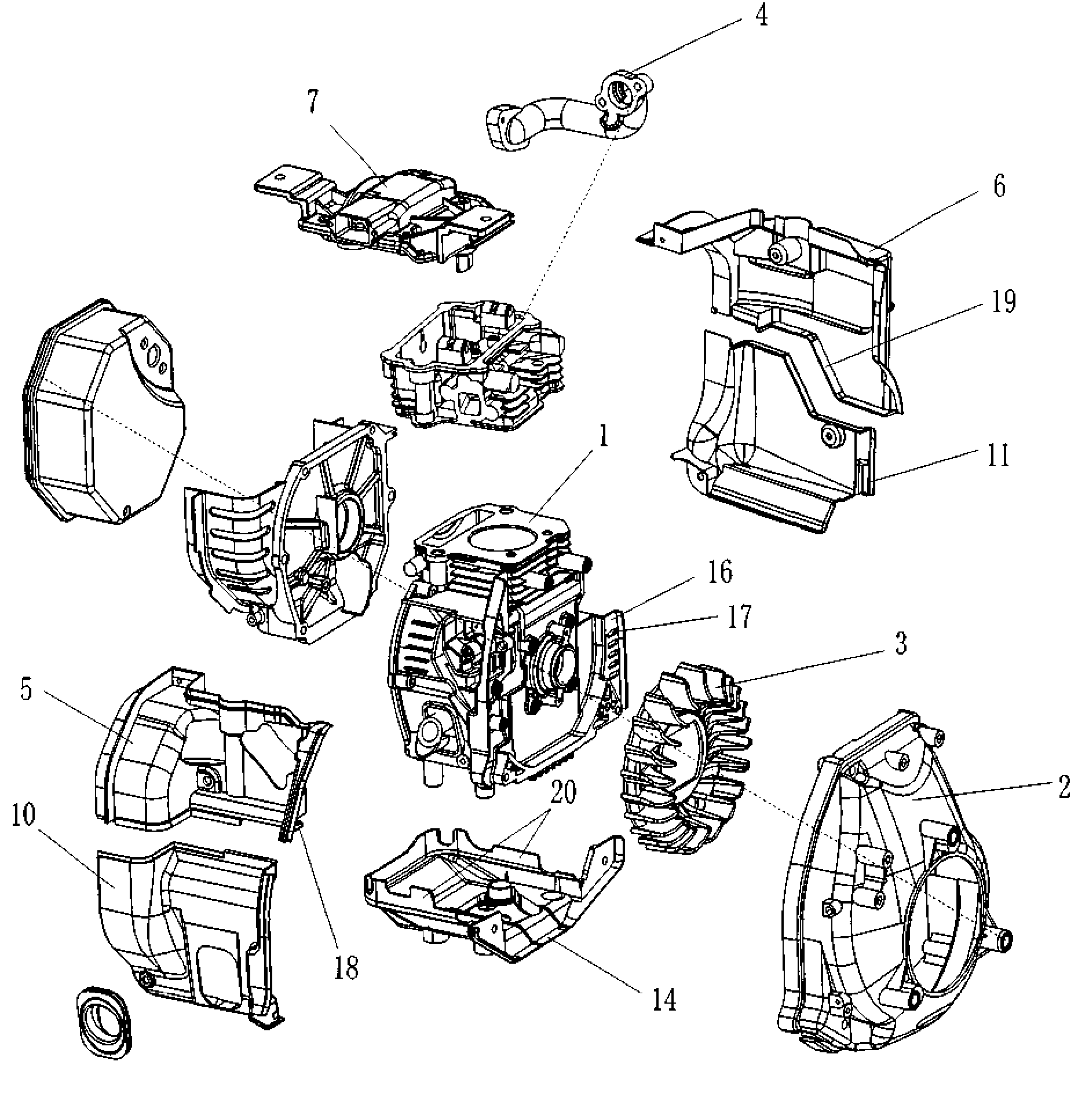
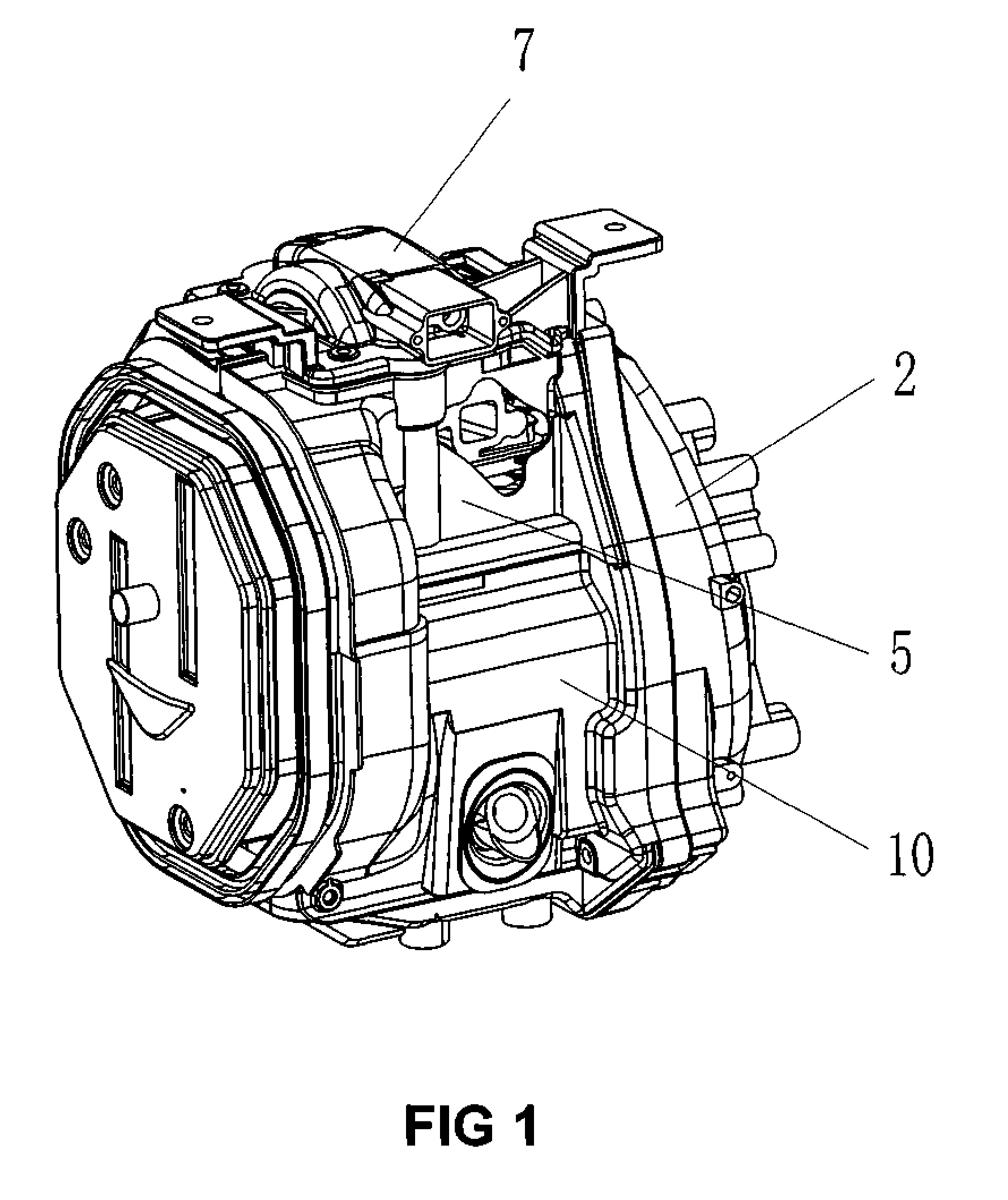
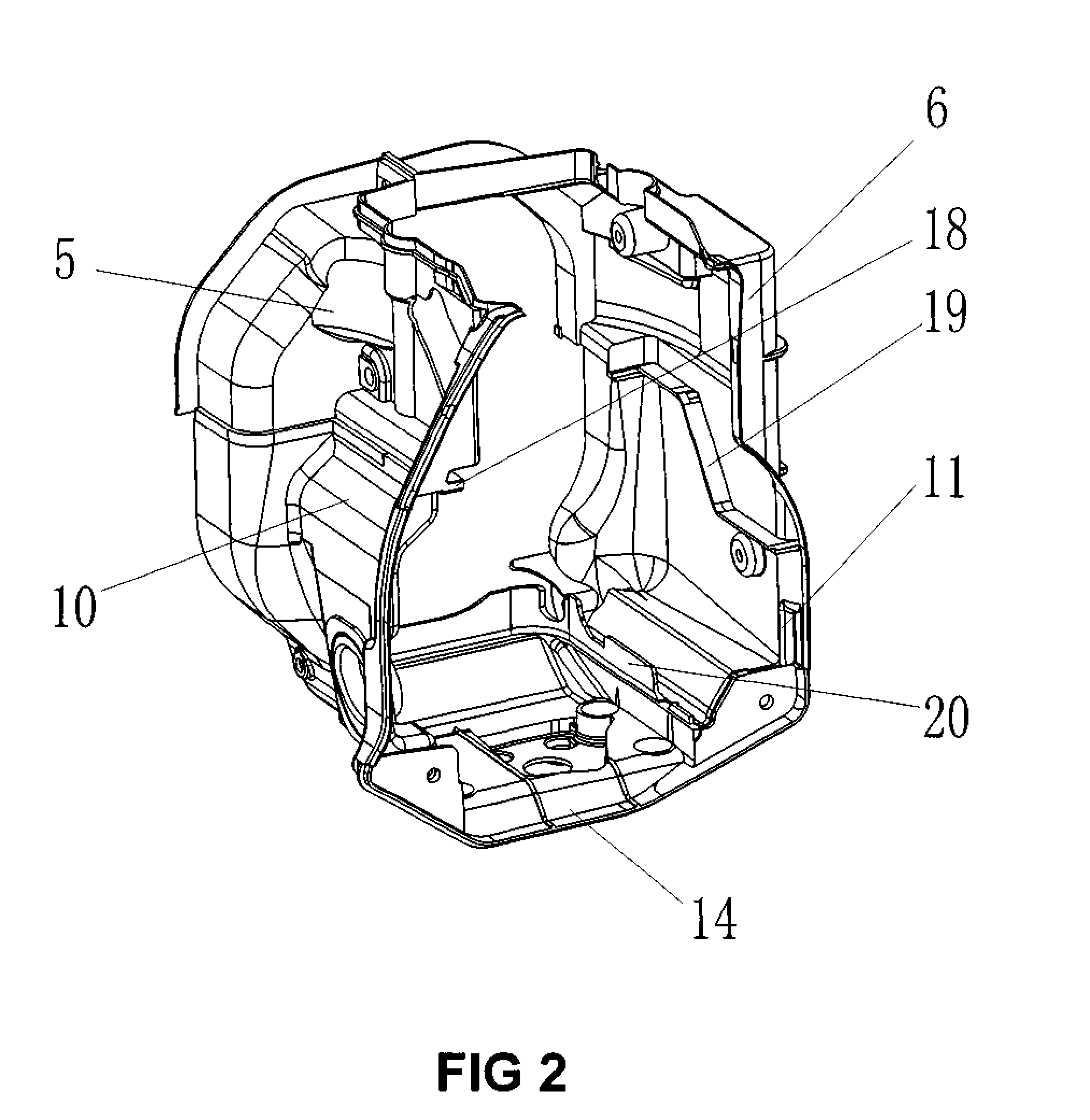
[0022]As shown in FIGS. 1 to 6, a portable engine, comprising an engine casing 1, an air deflector cover 2, a fan 3 and an exhaust pipe 4; a left convex rib 18 extends inward at the junction between the left upper baffle plate 5 and the left lower baffle plate 10 at the left part of the engine; a right convex rib 19 extends inward at the junction between the right upper baffle plate 6 and the right lower baffle plate 11 at the right part of the engine; a left convex rib 18 and a right convex rib 19 constitute two left and right upper air ducts 8 and 9 together with a cylinder head cover 7 and the engine casing 1; an upper convex rib 20 extends upward respectively on the left and right sides of the base plate of the engine; the bottom air duct 15 is composed of the two upper convex ribs 20 and the engine casing 1; the left convex rib 18 and the right convex rib 19 constitute two left and right lower air ducts together with the upper convex ribs 20 and the engine casing 1; and two low...


PUM


Abstract

A portable engine, comprising an engine casing, an air deflector cover, a fan and an exhaust pipe; a left upper baffle plate and a right upper baffle plate at the upper part of the engine constitute two left and right upper air ducts together with a cylinder head cover and the engine casing; a left lower baffle plate and a right lower baffle plate at the lower part of the engine constitute two left and right lower air ducts together with the engine casing; and a base plate of the engine and the engine casing constitute a bottom air duct. The portable engine can specifically cool each part through controlling air intake of each air duct, thus attaining better cooling effect for the engine.

Description

FIELD OF THE INVENTION[0001]The present invention relates to a portable engine.BACKGROUND OF THE INVENTION[0002]When an engine works, temperature of the cylinder cooling fin is very high, while temperature of the lower part of the casing is a little bit lower. A traditional portable engine adopts a design of an integrated air duct, which cools inner parts with cooling air drawn in by a fan and then expels through a vent groove. In such a way, direction and flow of cooling air cannot be well controlled, the cylinder head cover cannot be well cooled, and it is possible to heat the low-temperature part of the casing with hot air at the cylinder head cover.SUMMARY OF THE INVENTION[0003]A purpose of the present invention is to provide a portable engine, which has five air ducts and can specifically cool each part through controlling air intake of each air duct, thus attaining better cooling effect for the engine.[0004]An embodiment of the present invention is as follows: a portable engin...

Claims


Application Information

Patent Timeline
Patent Type & Authority Patents(United States)
IPC IPC(8): F01P1/02
CPCF01P1/02
Inventor MA, YUNFENG
Owner MA YUNFENG
Why Eureka
Try Eureka