Wound retractor device

a retractor and device technology, applied in the field of retractors, can solve the problems of difficult and cumbersome limited use of known retractors, and relatively high cos

Inactive Publication Date: 2009-07-14
ATROPOS LTD
View PDF379 Cites 231 Cited by
  • Summary
  • Abstract
  • Description
  • Claims
  • Application Information

AI Technical Summary

Benefits of technology

[0002]The invention relates to a retractor. In particular the invention relates to a retractor for retracting the margins of an incision or a natural bodily orifice to provide maximum exposure of an organ or body structures for examination and / or access for surgical procedures, while also providing protection for the exposed sides of the incised tissue.
[0078]gripping the gripping portion of the sleeve and pulling the sleeve upwardly to shorten an axial extent of the sleeve located between the distal member and the proximal member.
[0100]the retractor member being axially movable relative to the distal member to draw the proximal and distal members towards one another thereby shortening the axial extent of the retractor member between the proximal and distal members.
[0128]pulling the retractor member axially relative to the distal member to draw the proximal and distal members towards one another thereby shortening the axial extent of the retractor member between the proximal and distal members and retracting the incision.

Problems solved by technology

Some known retractors are difficult and cumbersome to use, and / or are relatively expensive.
In addition, some known retractors are limited to use with a particular size of incision and a particular patient anatomy.

Method used


Image

  • Wound retractor device
  • Wound retractor device
  • Wound retractor device

Examples


Embodiment Construction

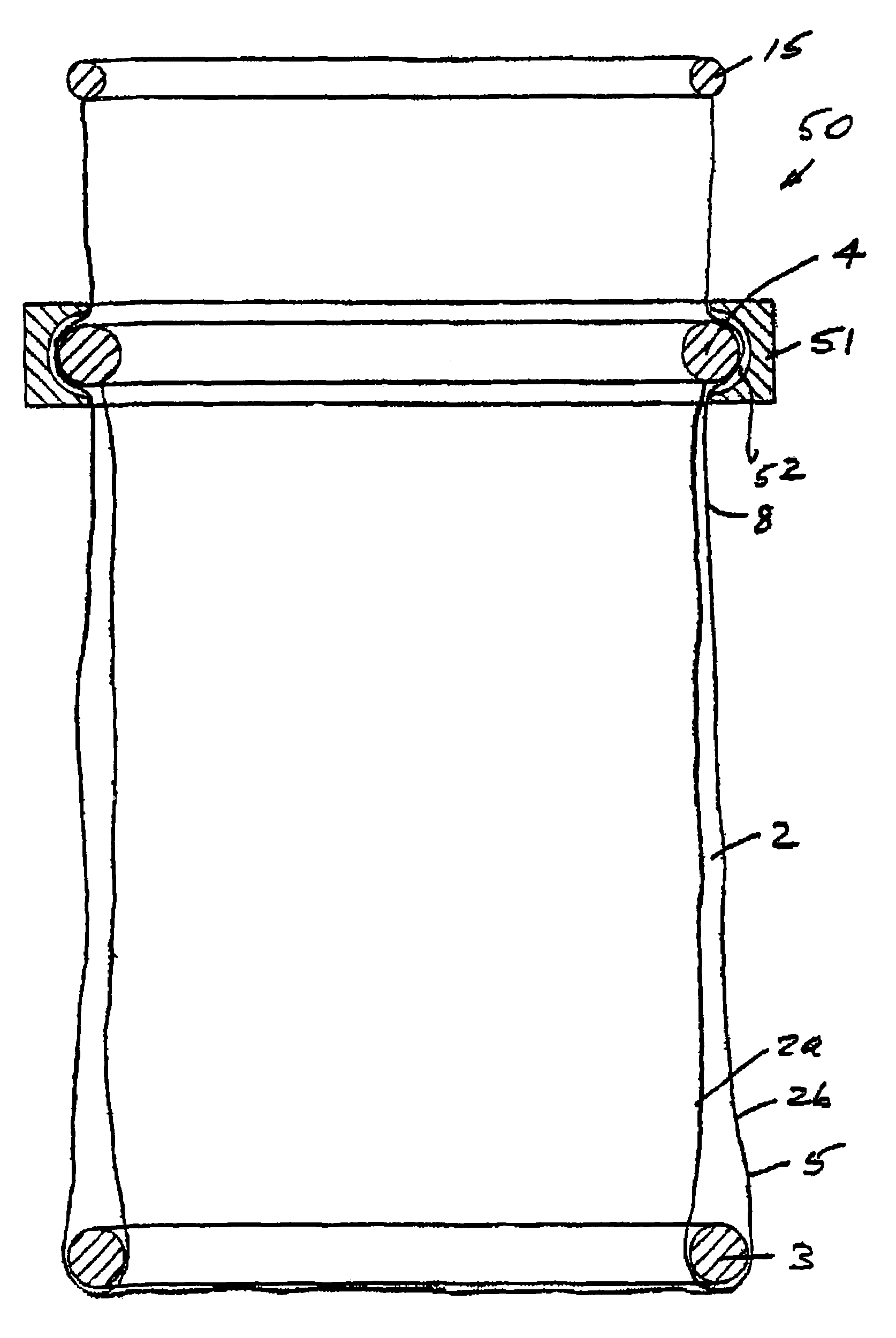
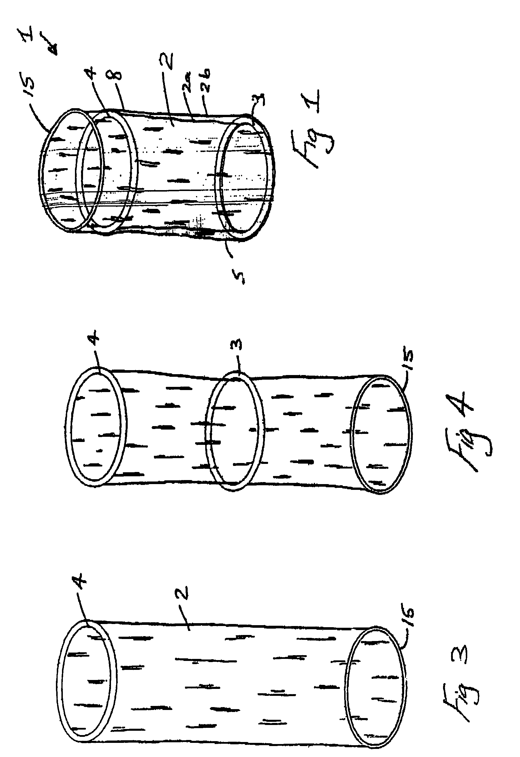
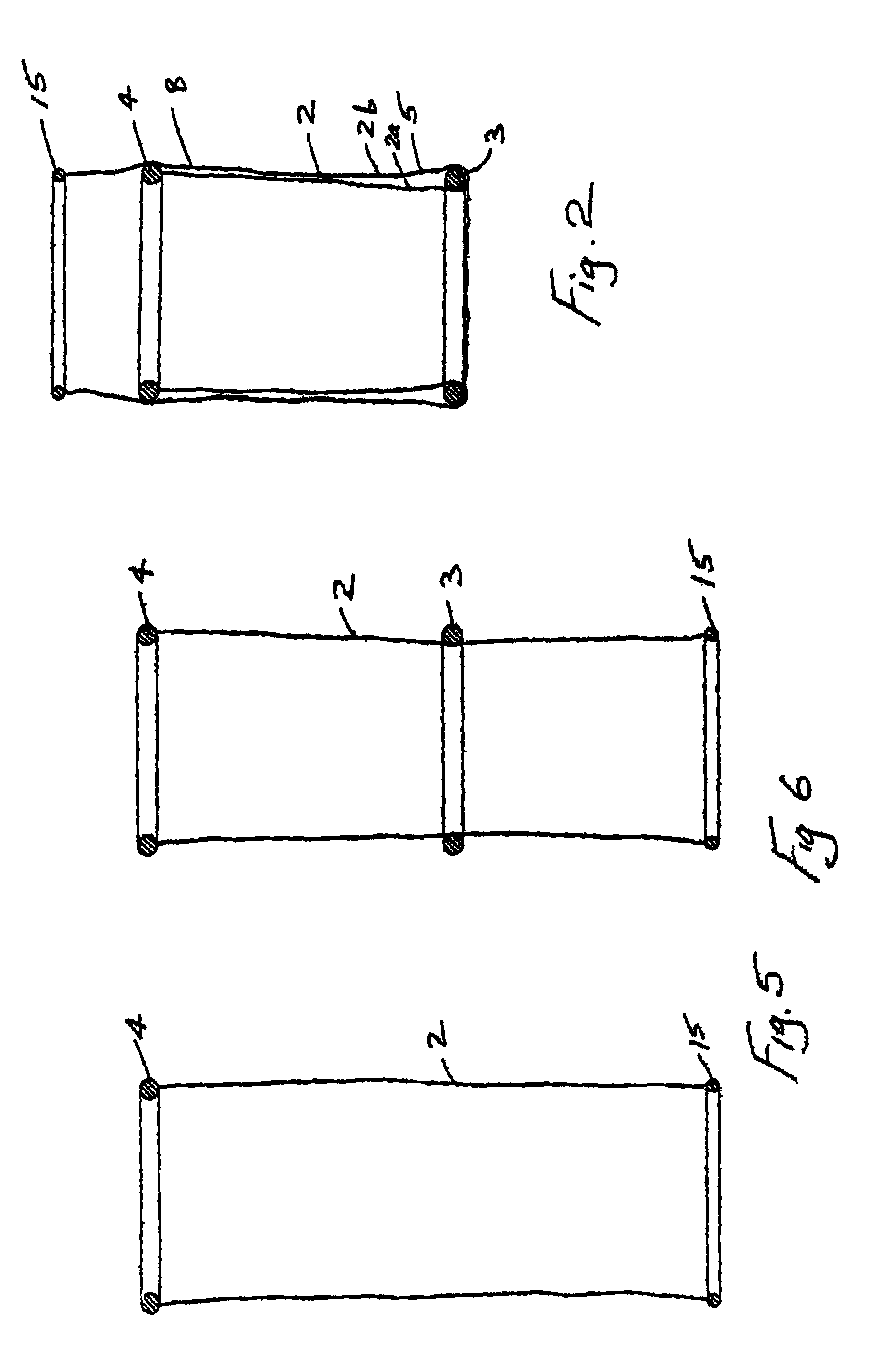
[0182]Referring to the drawings, and initially to FIGS. 1 to 10 thereof there is illustrated a device 1 comprising a retractor member provided by a sleeve 2, a distal member provided by a distal ring 3 of resilient material such as an O-ring and a proximal member provided by a proximal ring 4 which may also be an O-ring.

[0183]The sleeve 2 is of any suitable material such as of pliable plastics film material and comprises a distal portion 5 for insertion through an incision 6, in this case made in a patient's abdomen 7, and a proximal portion 8 for extending from the incision 6 and outside of the patient.

[0184]In this case the distal ring 3 is not fixed to the sleeve 2 but rather the sleeve is led around the ring 3 and is free to move axially relative to the distal ring 3 somewhat in the manner of a pulley. The proximal ring 4 is fixed to the sleeve 2, in this case at the proximal inner end thereof. The sleeve 2 terminates in a handle or gripping portion which in this case is reinfor...


PUM


Abstract

A wound protector and retractor device comprising a longitudinal axis, a distal member, a proximal member, and a sleeve extending at least between the distal member and the proximal member. The sleeve has a proximal gripping portion for pulling the sleeve upwardly to shorten an axial extent located between the distal member and the proximal member.

Description

CROSS REFERENCE TO RELATED APPLICATIONS[0001]This application is a continuation-in-part of U.S. application Ser. No. 10 / 133,979, filed on Apr. 29, 2002, now U.S. Pat. No. 6,846,287 which is a continuation of application Ser. No. 09 / 801,826, filed on Mar. 9, 2001, now abandoned, which is a continuation of PCT / IE99 / 00122, filed Dec. 1, 1999. This application is also a continuation-in-part of U.S. application Ser. No. 10 / 374,523, filed on Feb. 27, 2003, now U.S. Pat. No. 7,445,597 which is a continuation of U.S. application Ser. No. 09 / 849,341, filed on May 7, 2001, now U.S. Pat. No. 6,582,364, which is a continuation of U.S. application Ser. No. 09 / 688,138, filed Oct. 16, 2000, now U.S. Pat. No. 6,254,534. This application also claims the benefit of U.S. Provisional Application Nos. 60 / 415,780, filed on Oct. 4, 2002; 60 / 428,215, filed on Nov. 22, 2002; and 60 / 490,909, filed on Jul. 30, 2003. The contents of all of these provisional and nonprovisional applications are herein incorporat...

Claims


Application Information

Patent Timeline
Patent Type & Authority Patents(United States)
IPC IPC(8): A61B1/32A61B17/00A61B17/02A61B17/34
CPCA61B17/0293A61B17/3423A61B1/32A61B17/3431A61B2017/3482A61B2017/3484A61B2017/3492A61B2017/00557A61B17/3439A61B17/3462A61B2017/3443A61B17/3498A61B2017/0212A61B2017/0225
Inventor BONADIO, FRANKBUTLER, JOHNVAUGH, TREVORMACNALLY, SHANE JOSEPHREID, ALAN
Owner ATROPOS LTD
Why Eureka
Try Eureka