Coating apparatus and method

a coating apparatus and coating technology, applied in the direction of coatings, movable spraying apparatus, pretreated surfaces, etc., can solve the problems of high cost, waste of money, and difficult to apply a coating that is too thin or too thick, so as to minimize spraying, spatter, and slinging

Inactive Publication Date: 2009-07-14
PANKAKE EUGENE A
View PDF45 Cites 5 Cited by
  • Summary
  • Abstract
  • Description
  • Claims
  • Application Information

AI Technical Summary

Benefits of technology

[0011]Two embodiments of end seal design are described, each having preferably three seal lips, one of which differs in the center of its radius of curvature from the center of radius of curvature for the other two seal lips. The end seal is gently spring loaded. In this way the end seal provides a good seal and minimizes spray, spatter, and slinging, and can accommodate various plunge depths and can accommodate various angles of attack of a nozzle upon an application surface such as a web or applicator roll. The nozzle is able to have any of various user-determined angles of attack upon the application surface.
[0013]The end seals according to the invention are quite different from prior-art end seals. The end seals according to the invention are designed to permit ideal (or adequately close to ideal) geometry and force to be maintained between the end seal and the application surface for a very wide range of roll surface finishes, roll hardness and pressure feed application system bar angles using both a rigid pressure feed application system nozzle or a flexible nozzle. This is done by permitting the end seal surface contacting the application surface and the application surface to be concentric within a wide range of nozzle contact angles. In addition the end seal force to the application surface is controlled to a nearly constant value through a plunge into the application surface or nozzle deformation of approximately 0.03″ to 0.20″. This capability permits the contact angle of the nozzle to the application surface to vary through an approximate 10-degree range and permits nip forces to vary greatly with simple and manual coater control actuators (e.g. metering roll position actuators) or fully automated actuators.
[0014]In addition to the straightforward effects of nip pressure on metering the coating film thickness, the deformation of the flexible nozzle creates another powerful dependent actuator. This actuator is the deformation of the nozzle creating different geometry at the nip point very much like changing the diameter of the roll. In conventional coating it is common to set up the process with specific roll diameters to achieve specific goals. If a different coating with different requirements is applied it may be necessary to change one or more of the roll diameter, the surface finish or the roll cover thickness and / or roll cover hardness. The ability to change the nozzle angle and plunge significantly and on the fly permits a more powerful tool for film thickness control without the need to stop the production process. A typical roll coating process will have roll plunge values of 0.010″ to 0.035″. It is very rare that a process is outside of this range. The greater the plunge distance, the less inherent variability from roll swell, roll runout, roll bearing runout, cover hardness variability, and roll cover thickness variability that is translated to coating film thickness variability. The pressure feed application system coating technology with the end seals according to the invention can permit 0.170″ plunge or greater. This results in a reduction in film thickness variability to many times less than can be achieved with any type of conventional roll coating. The typical variability for roll and bearings can easily be 0.002″. If the total deformation during the roll coating process is 0.020″ with roll variability of 0.004″ (for two rolls) product variability will be much greater than a coating process with roll variability of 0.001″ (for one roll) with a 0.170″ total deformation targeting the same nominal film thickness.
[0015]This translates to savings in several ways. First, it is necessary for any company that applies coating to substrates to ensure that the film thickness is no less than the lowest acceptable film thickness. It is necessary to do this regardless of whether the material is siding, roofing, fin stock, food containers, appliance or automobile body stock. Any observed variability in film thickness requires increasing the amount of coating that must be applied, so as to protect this bottom end, namely, to ensure that the film thickness is no less than the lowest acceptable film thickness. Variability of plus or minus 5% with a normal distribution in the nominal thickness requires a cushion which is typically 5%. In addition, the variability above the lowest thickness in a coil is unnecessary material applied. Thus 5% of the material applied is applied unnecessarily, just to protect the bottom specification, that is, to ensure that the film thickness is no less than the lowest acceptable film thickness.
[0017]For a given applicator roll, its first few hours in service are hours in which the roll will frequently be seen to swell and to soften. During this time the applied film thickness is increasing. The operator is required to monitor and make adjustments based on the next end of coil film thickness, or a closed-loop film thickness control system is required to make corrections. The flexible nozzle design according to the invention permits the use of a very hard polymer covering (that is, a covering that does not swell or swells very little), or permits the use of a non-flexible applicator roll such as a chrome roll. A combination of elimination of at least one set of roll variability, the large increase in deformation capability, the ability to use rolls that do not change shape or hardness, and the ability to control nip shape geometry, provides the ability to precisely control film thickness from beginning to end of a coil at levels of precision not conceivable with conventional roll coating. The flexible nozzle can permit effective nip geometries from approximately the equivalent of a 20-inch to less than a 4-inch diameter metering roll. This provides an enormous range for film thickness control.

Problems solved by technology

Prior-art coating production lines, however, have had many problems.
One problem is that it is all too easy to apply a coating that is too thin or too thick.
If the coating is thicker than necessary, money is wasted because too much coating gets used.
Another problem is that with many coaters, there can be unevenness in the coating, with puckering, gapping, voids, and the like.
Still another problem is that with many coaters, there are wear items that wear out quickly.
When a wear item wears out, this forces the production line to be shut down.
Finally, the need to make a change in the coating fluid (e.g. a change in paint color) may also require shutting down the production line.
A moment's reflection will prompt a realization that even with ideally selected materials and geometry for the leading and trailing edges of the nozzle, a nontrivial design problem remains.
If little or no thought is given to the designs of the two ends of the elongated nozzle, then coating (e.g. paint) is likely to leak out the ends, and indeed may spray out depending on the pressure in the nozzle.
In the case where a transfer roll is used to transfer coating from the nozzle to the web, any excessive amount of coating leaking out the ends is likely to “sling” out due to centrifugal force, traveling in uncontrolled directions.
On the other hand if the nozzle is applying coating directly to a web, then any leaking excess coating will lead to unevenness and possibly excess material along the edges of the web.
Unfortunately, many end seal designs that have been proposed have not served their purpose well.
Some end seal designs are wear items, wearing out often and requiring replacement.
Other end seal designs will “plunge” into the flexible surface of an applicator roll and will cause the applicator roll to wear and to lose surface material due to the wear.
Still other end seal designs are extremely sensitive to even the smallest changes in spacing and geometry as between the nozzle and the web or applicator roll; with some end seal designs even a small change can lead to excessive wear on the one hand or excessive leakage on the other hand.
Yet another problem in the design of coaters is that it is desired to have close control over the manner in which the nozzle applies the coating to the surface being coated (e.g. the web or applicator roll).
Close control of such a distance is not easy, because of manufacturing tolerances, wear and expansion of transfer rollers, and other factors.
Even if one is able to control such a distance closely, this does not control, as closely as one might wish, the manner in which the coating is applied to the surface being coated.

Method used


Image

  • Coating apparatus and method
  • Coating apparatus and method
  • Coating apparatus and method

Examples


first embodiment

[0056]FIG. 18 is a perspective view of an end seal design according to the invention. Omitted for clarity in FIG. 18 are the back seal 7 and trailing edge of the nozzle 55, which if shown would extend to the lower left in FIG. 18. First seal lip 111 may be seen, along with second seal lip 112 and third seal lip 113. Applicator roll 6 is likewise omitted for clarity in FIG. 18. Its direction of movement is toward the lower left in FIG. 18.

[0057]FIG. 20 is an exploded view of the end seal of FIG. 18. In this view we can see a springy section 93 which tends to urge seal top 34 (which incorporates lips 111, 112, 113) upwards toward the roll 6 that is omitted for clarity in this FIG. 20. In addition, a spring 38 permits an adjustable force upwards on the end of the seal top 34 as well (that is, on the trailing edge of the seal), again toward the roll 6. This is the same spring 38 the exterior portion of which which was visible in FIG. 3.

[0058]It is evident from FIG. 18 that the first sea...

second embodiment

[0059]FIG. 22 shows a perspective view of an end seal design according to the invention. As in FIG. 20, back seal 7 and trailing edge of nozzle 55 extend toward the lower left in FIG. 22 and are omitted for clarity. As detailed in FIG. 23, there are again lips 111, 112, 113 which help to seal the end of the nozzle. As in FIG. 20, a spring 38 permits adjustment of the force upwards, on the end of the seal at its trailing edge, toward the applicator roll 6, omitted for clarity. As in FIG. 20, the applicator roll 6, if visible, would move downwards and to the left in FIG. 22.

[0060]The invention, as portrayed in the figures, will now be discussed in great detail, starting with the nozzle locking and angle adjustment features and then turning to the end seal features.

Nozzle Locking and Angle Adjustment

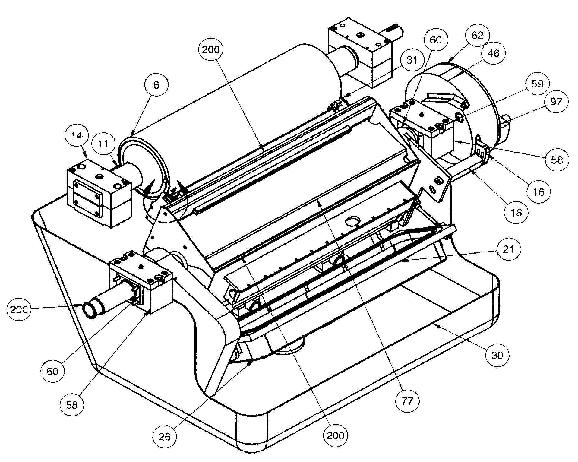
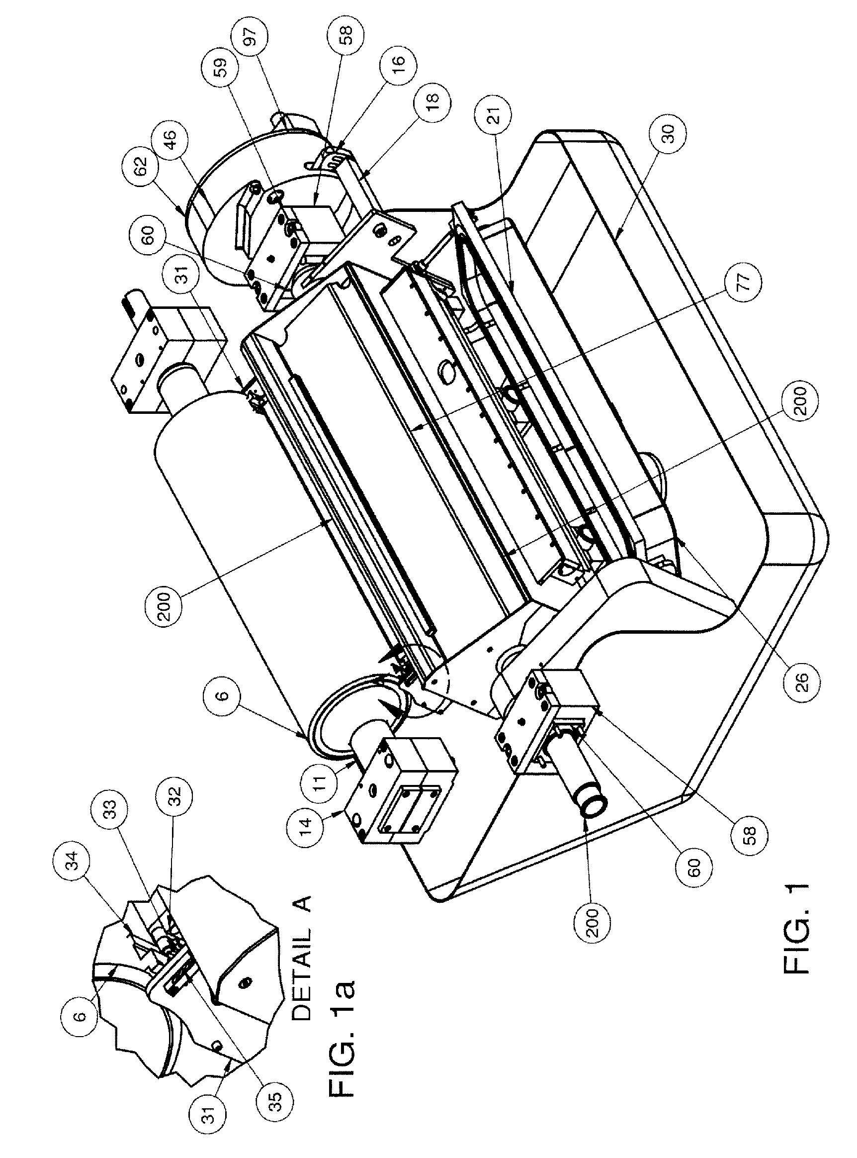
[0061]The pressure feed application system bar locking device 97 is shown in FIGS. 1, 4, 5, 6, 7, 8, 9 and 11. It is used to precisely position the pressure feed application system bar nozz...


PUM


Abstract

Two embodiments of end seal design are described, each having preferably three seal lips, one of which differs in the center of its radius of curvature from the center of radius of curvature for the other two seal lips. The end seal is gently spring loaded. In this way the end seal provides a good seal and minimizes spray, spatter, and slinging, and can accommodate various plunge depths and can accommodate various angles of attack of a nozzle upon an application surface such as a web or applicator roll. The nozzle is able to have any of various user-determined angles of attack upon the application surface.

Description

CROSS-REFERENCE TO RELATED APPLICATIONS[0001]This application claims priority from U.S. application No. 60 / 511,146 filed Oct. 14, 2003, U.S. application No. 60 / 520,151 filed Nov. 14, 2003, U.S. application No. 60 / 527,894 filed Dec. 8, 2003, U.S. application No. 60 / 547,336 filed Feb. 24, 2004, and U.S. application No. 60 / 617,363, filed Oct. 8, 2004, each of which is hereby incorporated herein by reference for all purposes. This application is a continuation-in-part of U.S. application Ser. No. 10 / 707,278 filed Dec. 2, 2003, now U.S. Pat. No. 6,837,932 which is a continuation of U.S. application Ser. No. 09 / 678,228 Oct. 2, 2000, now U.S. Pat. No. 6,656,529 issued Dec. 2, 2003, which is a continuation of U.S. application No. PCT / US99 / 10819 filed May 18, 1999, which claims priority from U.S. application No. 60 / 086,047 filed on May 19, 1998, each of which is hereby incorporated herein by reference for all purposes.BACKGROUND OF THE INVENTION[0002]The invention relates generally to the ap...

Claims


Application Information

Patent Timeline
Patent Type & Authority Patents(United States)
IPC IPC(8): B05B3/02B05C1/08B05C3/12B05C3/18B05C9/04
CPCB05C1/0813B05C1/0839B05C3/18B05C1/0873B05C9/04B05C3/125
Inventor PANKAKE, EUGENE A
Owner PANKAKE EUGENE A
Why Eureka
Try Eureka