Wireless sensor system and bearing assembly equipped with the same

a sensor system and bearing technology, applied in the direction of fluid pressure measurement, instruments, inflated body pressure measurement, etc., can solve the problems of unbalanced wheel rotation, unbalanced sensor rotation, environmental contamination, etc., to minimize electric power consumption, facilitate maintenance of wireless senor system, and advantageously reduce electromagnetic waves

Inactive Publication Date: 2009-07-14
NTN CORP
View PDF40 Cites 29 Cited by
  • Summary
  • Abstract
  • Description
  • Claims
  • Application Information

AI Technical Summary

Benefits of technology

[0009]In view of the foregoing, the present invention has for its essential object to provide an improved wireless sensor system, which is light-weighted and compact in structure and can easily be serviced, and which can be actively used in communication at any time, while being capable of accomplishing both supply of an electric power to a plurality of wireless sensors and transmission of wireless sensor signals.
[0010]Another important object of the present invention is to provide an improved wireless sensor system, which is light-weighted and compact in structure and can easily be serviced, and which can be actively used in communication at any time, while being capable of accomplishing both supply of an electric power to a plurality of wireless sensor units and transmission of wireless sensor signals.
[0011]A further object of the present invention is to provide a wireless sensor system of an automobile vehicle, which is capable of transmitting a wireless sensor signal indicative of, for example, the tire pressure and / or the number of revolutions of the vehicle wheel, reduction in cost and maintenance-free as a result of elimination of use of any battery, securement of a balanced wheel rotation resulting from reduction in weight and operation of the sensor even at an extremely low speed rotation of the wheel.

Problems solved by technology

However, it has often been experienced that the wired communication system is available only where wiring is possible, and where no wiring is possible, a wireless sensor system that transmits sensor signals wireless in the form of wireless electromagnetic signals is available.
The sensor system utilizing the battery has the following problems.
In the first place, since the battery has a limited life, routine battery replacement is necessary resulting in complicated and cumbersome management of the lifetime of the battery.
Other problems are associated with the environmental contamination resulting from disposal of the battery.
In addition, where the rotation sensor utilizing the battery is used in a wheel support bearing assembly or in detecting the tire pressure, an unbalanced wheel rotation may occur as a result of increase of the sensor weight.
Therefore, the detection of the number of revolutions of the wheel tends to be unstable when the wheel rotates at an extremely low speed approximating to a halt, although the rotation sensor works satisfactorily when the wheel rotates at a speed equal to or higher than about 10 Km / h, at which the ABS is often activated.
Also, this type of the rotation sensor cannot be used to detect other target parameters such as the temperature.
As discussed above, the self-generating rotation sensor is not capable of generating or supplying an electric power in some cases.
Particularly, where sensors other than a rotation-detecting sensor are utilized, it has been found difficult to secure supply of an electric power to the sensors and transmission of sensor signals from those sensors.

Method used


Image

  • Wireless sensor system and bearing assembly equipped with the same
  • Wireless sensor system and bearing assembly equipped with the same
  • Wireless sensor system and bearing assembly equipped with the same

Examples


second embodiment

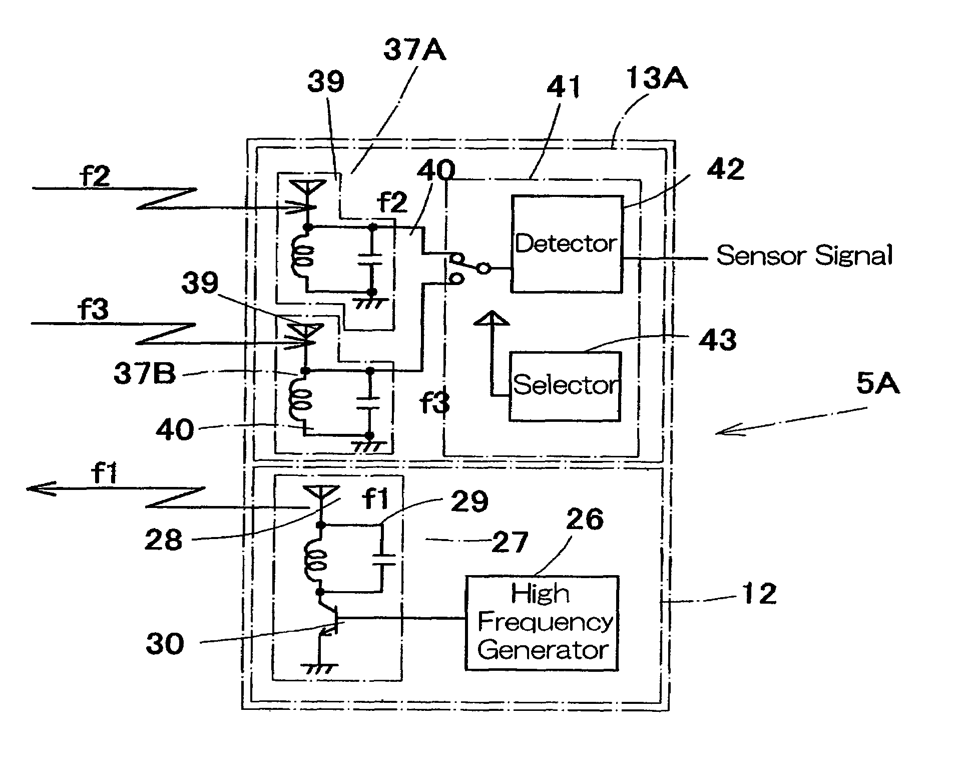
[0074]In this second embodiment, when the switching element 43 of the switching detector 41 connects the tuning circuit 37A to the detecting element 42, the detecting element 42 detects a signal of the frequency f2 which is fed wireless to the tuning circuit 37A from the wireless sensor unit 4A for detecting the number of revolutions. On the other hand, when the switching element 43 connects the tuning circuit 37B to the detecting element 42, the detecting element 42 detects a signal of the frequency f3 which is fed wireless to the tuning circuit 37B from the wireless sensor unit 4B for detecting the number of revolutions.

[0075]According to the second embodiment shown in and described with reference to FIG. 3, the respective electromagnetic waves of the natural frequencies f2 and f3 transmitted wireless from the associated wireless sensor units 4A and 4B can be discriminately detected by the single detecting element 42 in the sensor signal receiving unit 5A, the sensor signal receiv...

third embodiment

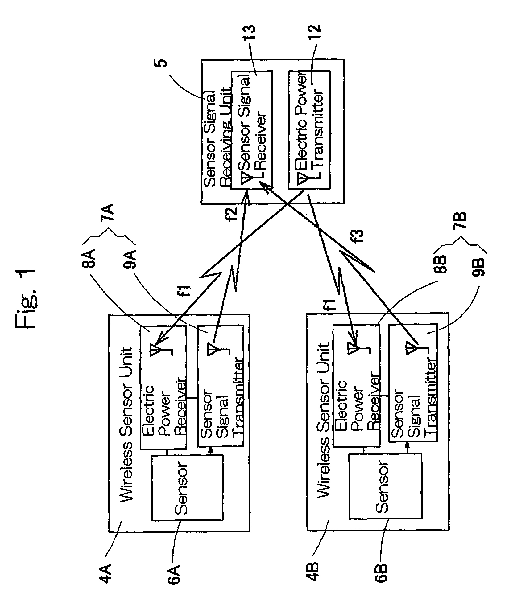
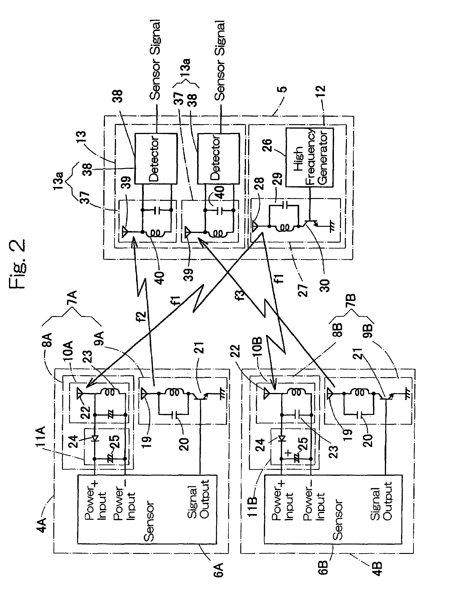
[0096]The sensor signal receiving unit 5 is installed at a suitable place within the machine plant 53, where the sensor signal receiving unit 5 receives the sensor signals from the wireless sensor units 4A and 4B and transmits the electric operating power to the wireless sensor units 4A and 4B. Unless otherwise specified, this third embodiment is substantially similar in structure to the embodiment shown in and described with reference to FIGS. 1 and 2.

[0097]According to the third embodiment, the respective sensor signals outputted from the wireless sensor units 4A and 4B, which are mounted on the associated rolling bearings 51 and 52 within the machine plant 53, are received by the common sensor signal receiving unit 5 and, concurrently, the electric operating power required to drive the wireless sensor units 4A and 4B can be supplied wireless from the common sensor signal receiving unit 5 to the wireless sensor units 4A and 4B.

[0098]It is to be noted that although in the embodimen...

first embodiment

[0104]It is also to be noted that one of the wireless sensor units 4A and 4B employed in the present invention shown in FIG. 1 may be of a design including the plural sensors 6C to 6E shown in FIG. 8. In such case, the use is preferred of the signal coordinator 60.


PUM

PropertyMeasurementUnit
electric operatingaaaaaaaaaa
electric operating poweraaaaaaaaaa
natural frequenciesaaaaaaaaaa

Abstract

A wireless sensor system of the present invention includes wireless sensor units (4A, 4B) and a sensor signal receiving unit (5). The sensor units (4A, 4B) have sensors (6A, 6B), an electric power receiver (8A, 8B) for securing the electric power from an electromagnetic wave of a power feeding frequency f1 through a tuning circuit and a detecting and rectifying circuit, and sensor signal transmitters (9A, 9B) for transmitting the signals outputted from the sensors as a wireless sensor signal of the electromagnetic wave of unique frequencies f2 and f3 different from the power feeding frequency f1. The sensor signal receiving unit (5) has an electric power transmitter (12) for transmitting the electromagnetic wave of the power feeding frequency f1 to the units (4A, 4B) and a sensor signal receiver (13) for receiving wireless the sensor signals of the respective frequencies f2 and f3 transmitted from the units (4A, 4B).

Description

FIELD OF THE INVENTION[0001]The present invention generally relates to a wireless sensor system for wireless receiving a detection signal indicative of, for example, the tire pressure or the number of revolutions of a wheel in an automotive vehicle. The present invention also relates to a bearing assembly equipped with such wireless sensor system and a wheel support bearing assembly equipped with such wireless sensor system.BACKGROUND ART[0002]It is known that various sensors are employed in automotive vehicles and various industrial machines to detect various target parameters such as the number of revolutions, the temperature and the vibration of bearing assembly and / or any other movable component parts with a view to controlling of the machines and supervision of machine statuses. Outputs generated from those sensors are generally transmitted through a wired communication system. However, it has often been experienced that the wired communication system is available only where wi...

Claims


Application Information

Patent Timeline
Patent Type & Authority Patents(United States)
IPC IPC(8): B60C23/00G01P3/487B60C23/02B60C23/04G01L17/00G01P3/44G08C17/02
CPCB60C23/041B60C23/0413B60C23/0418F16C41/008B60C23/0433G01P3/443G01P3/446B60C23/042B60C23/0483F16C19/06F16C19/186F16C2326/02
Inventor SAHASHI, KOJIOKADA, KOICHIMIZUTANI, MASATOSHI
Owner NTN CORP
Why Eureka
Try Eureka