Supercharge Your Innovation With Domain-Expert AI Agents!

Modulized antenna structure

a module and antenna technology, applied in the direction of individual energized antenna arrays, portable computers, instruments, etc., can solve the problem of consuming a lot of time to assemble the antenna modul

Inactive Publication Date: 2009-07-14
COMPAL ELECTRONICS INC
View PDF4 Cites 4 Cited by
  • Summary
  • Abstract
  • Description
  • Claims
  • Application Information

AI Technical Summary

Benefits of technology

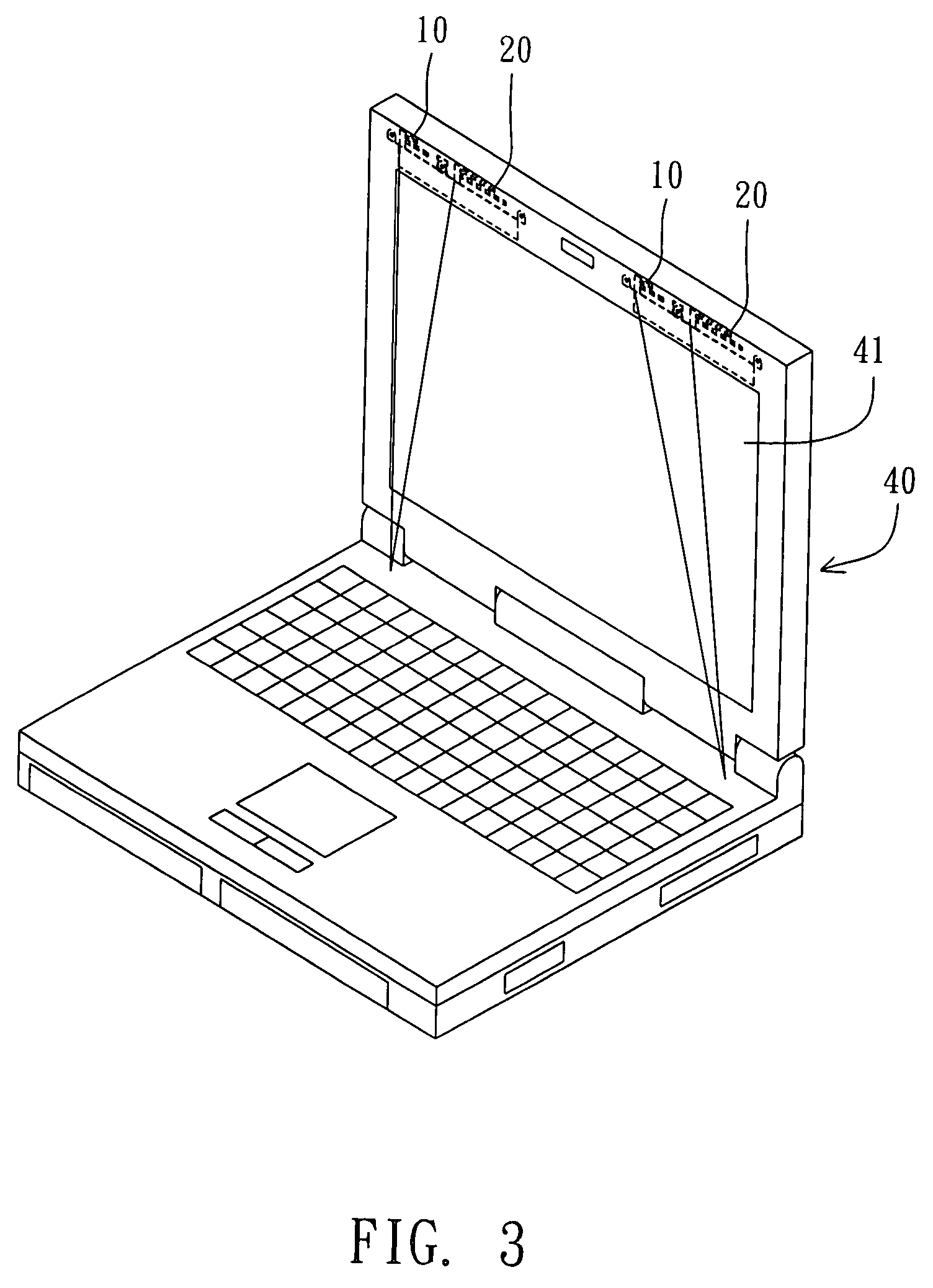
The present invention provides a modulized antenna structure that allows for flexible configuration based on the product's requirements. It also effectively constraints the position of the antenna module to improve its receiving effectiveness and facilitate assembly, reducing manufacturing costs. The modulized antenna structure comprises a first antenna module, a second antenna module, and a fixed component that partially overlaps with the second antenna modules and is assembled on an electronic device's screen. This results in a protruding wall that effectively constrains the position of the antenna module.

Problems solved by technology

Accordingly, it is rather time consuming to assemble the antenna module mentioned above.

Method used


Image

  • Modulized antenna structure
  • Modulized antenna structure
  • Modulized antenna structure

Examples


Embodiment Construction

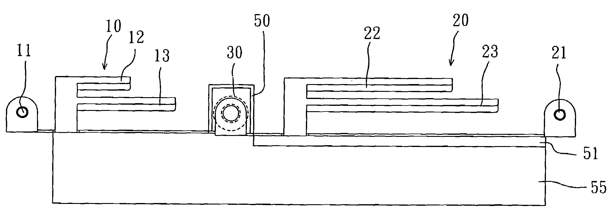
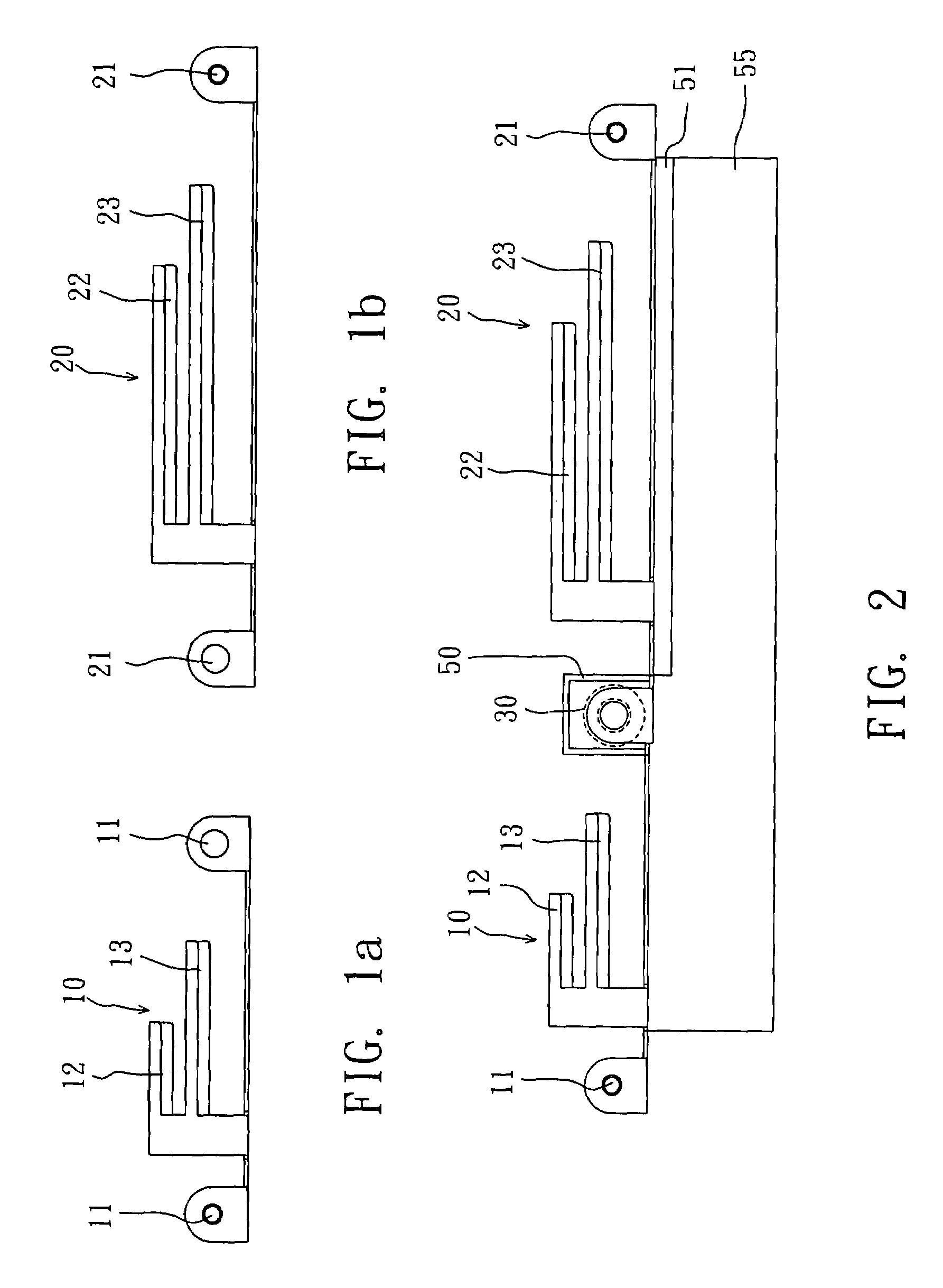
[0018]Referring to FIGS. 1(a), 1(b) and 2, wherein FIG. 1(a) schematically shows a first antenna module of a modulized antenna structure according to a preferred embodiment of the present invention; FIG. 1(b) schematically shows a second antenna module of a modulized antenna structure according to a preferred embodiment of the present invention; and FIG. 2 is a schematic diagram showing the overlapping of the first antenna module and the second antenna module of the present invention while they are being assembled. As shown in the drawings, the modulized antenna structure of the present invention comprises a first antenna module 10, a second antenna module 20, and a fixed component 30.

[0019]Wherein, the first antenna module 10 receives a first transmission signal in which at least one side of the first antenna module 10 has a first opening 11. Two openings 11 are exemplified in the present embodiment for easy explanation, but it is not limited to two openings. Here, the first antenn...


PUM


Abstract

The present invention relates to a modulized antenna structure, which comprises: a first antenna module for receiving a first transmission signal in which at least one side of the first antenna module has a first opening; a second antenna module for receiving a second transmission signal in which at least one side of the second antenna module has a second opening; and a fixed component, while being assembled, with the fixed component, the first antenna module is partially overlapped with the second antenna modules and the first opening is fully overlapped with the second opening, thus the fixed component can pass through the first and second openings and be fixed on the screen of an electronic device.

Description

BACKGROUND OF THE INVENTION[0001]1. Field of the Invention[0002]The present invention relates to a modulized antenna structure, and more particularly, to a modulized antenna structure in which two different antenna modules are partially overlapped, such that the antenna structure is smaller and easier to assemble.[0003]2. Description of the Related Art[0004]For adapting to the prevalence of the Digital Video Broadcast (DVB), Global Positioning System (GPS) or Wireless Fidelity (Wi-Fi) wireless local area networks, it is common to add one antenna module on the notebook computers to receive the aforementioned DVB, GPS or Wi-Fi's wireless signals.[0005]For example, an integrated multi-frequency antenna for notebook computers had been disclosed by the “Integrated Multi-frequency Antenna for Notebook Computers” in the approved R.O.C. Patent No. 583785 (applied on Apr. 8, 2003 and published on Apr. 11, 2004). Here, the notebook computer comprises a screen and a screen case frame, and the ...

Claims


Application Information

Patent Timeline
Patent Type & Authority Patents(United States)
IPC IPC(8): H01Q1/24H01Q1/22H01Q21/06
CPCG06F1/1616G06F1/1698H01Q1/2266H01Q5/40H01Q21/30H01Q5/371H01Q1/521
Inventor YU, JEN-HUAN
Owner COMPAL ELECTRONICS INC
Features
  • R&D
  • Intellectual Property
  • Life Sciences
  • Materials
  • Tech Scout
  • Unparalleled Data Quality
  • Higher Quality Content
  • 60% Fewer Hallucinations
Learn More