Notched surface-mounted anchors and wall anchor systems using the same

a technology of surface-mounted anchors and wall anchors, which is applied in the direction of foundation engineering, building components, structural elements, etc., can solve the problems of system insufficient insulation integrity, loosening of studs, and hampered installation

Inactive Publication Date: 2009-07-21
HOHMANN & BARNARD INC
View PDF26 Cites 58 Cited by
  • Summary
  • Abstract
  • Description
  • Claims
  • Application Information

AI Technical Summary

Benefits of technology

[0044]In general terms, the invention disclosed hereby is a unique surface mounted wall anchor and an anchoring system employing the same. The wall anchor is a sheetmetal device which is described herein as functioning with various wire formative veneer ties. In two embodiments, enfolded legs have a projecting portion and a nonprojecting portion. The folded construction of the wall tie enables the junctures of the legs and the base of the wall anchor to be located inboard from the periphery of the wall anchor. During formation of the wall anchor, the outer surface of the nonprojecting portion of the enfolded leg and the underside of the base are caused to be coplanar. Upon installation, the coplanar elements act to seal the insertion point where the legs enter into the exterior layer of building materials on the inner wythe. This sealing effect precludes the penetration of air, moisture, and water vapor into the inner wythe structure. In all of the embodiments shown, the legs are formed to fully or partially sheath the mounting hardware of the wall anchor. The sheathing function reduces the openings in the insulation required for installing the wall anchor.
[0045]In the first embodiment, the folded wall anchor is adapted from the earlier inventions of Schwalberg, U.S. Pat. No. 4,021,990 and of Hohmann, U.S. Pat. No. 4,875,319, see supra. Here it is seen that the double folded wall anchor (with legs moved inboard) have deeply impressed ribs alongside the bail, which creates a wall anchor construct of superior strength. This construct is applied to an insulated dry wall inner wythe having insulation over wallboard cavity, and an outer wythe of brick. The channel in the projecting portion of the legs ensheaths the interior side of the mounting hardware and the notch minimizes penetration through wallboard and the associated waterproofing membrane.
[0049]It is yet another object of the present invention to provide an anchoring system which is resistive to water penetrating the wallboard protective covering, to high levels of tension and compression and, further, to prevent disengagement under seismic or other severe environmental conditions.
[0050]It is still yet another object of the present invention to provide an anchoring system which is constructed to maintain insulation and waterproofing membrane integrity by preventing air and water penetration thereinto.
[0053]It is yet another feature of the present invention that the bearing area between the wall anchor and the veneer tie spreads the forces thereacross and avoids pin-point loading.

Problems solved by technology

However, under certain conditions, the system did not sufficiently maintain the integrity of the insulation.
Besides earthquake protection, the failure of several high-rise buildings to withstand wind and other lateral forces resulted in the incorporation of a continuous wire reinforcement requirement in the Uniform Building Code provisions.
In general, the pintle-receiving sheetmetal version of the Seismiclip interlock system served well, but in addition to the insulation integrity problem, installations were hampered by mortar buildup interfering with pintle leg insertion.
This resulted, upon experiencing lateral forces over time, in the loosening of the stud.
While the gapping was largely resolved by placing a self-sealing, dual-barrier polymeric membrane at the site of the legs and the mounting hardware, with increasing thickness in insulation, this patchwork became less desirable.
However, as there is no thermal break, a concomitant loss of the insulative integrity results.
On the other hand, contractors find that heavy wire anchors, with diameters approaching the mortar layer height specification, frequently result in misalignment.
However, the above-described technology did not address the adaption thereof to surface mounted devices.

Method used


Image

  • Notched surface-mounted anchors and wall anchor systems using the same
  • Notched surface-mounted anchors and wall anchor systems using the same
  • Notched surface-mounted anchors and wall anchor systems using the same

Examples


first embodiment

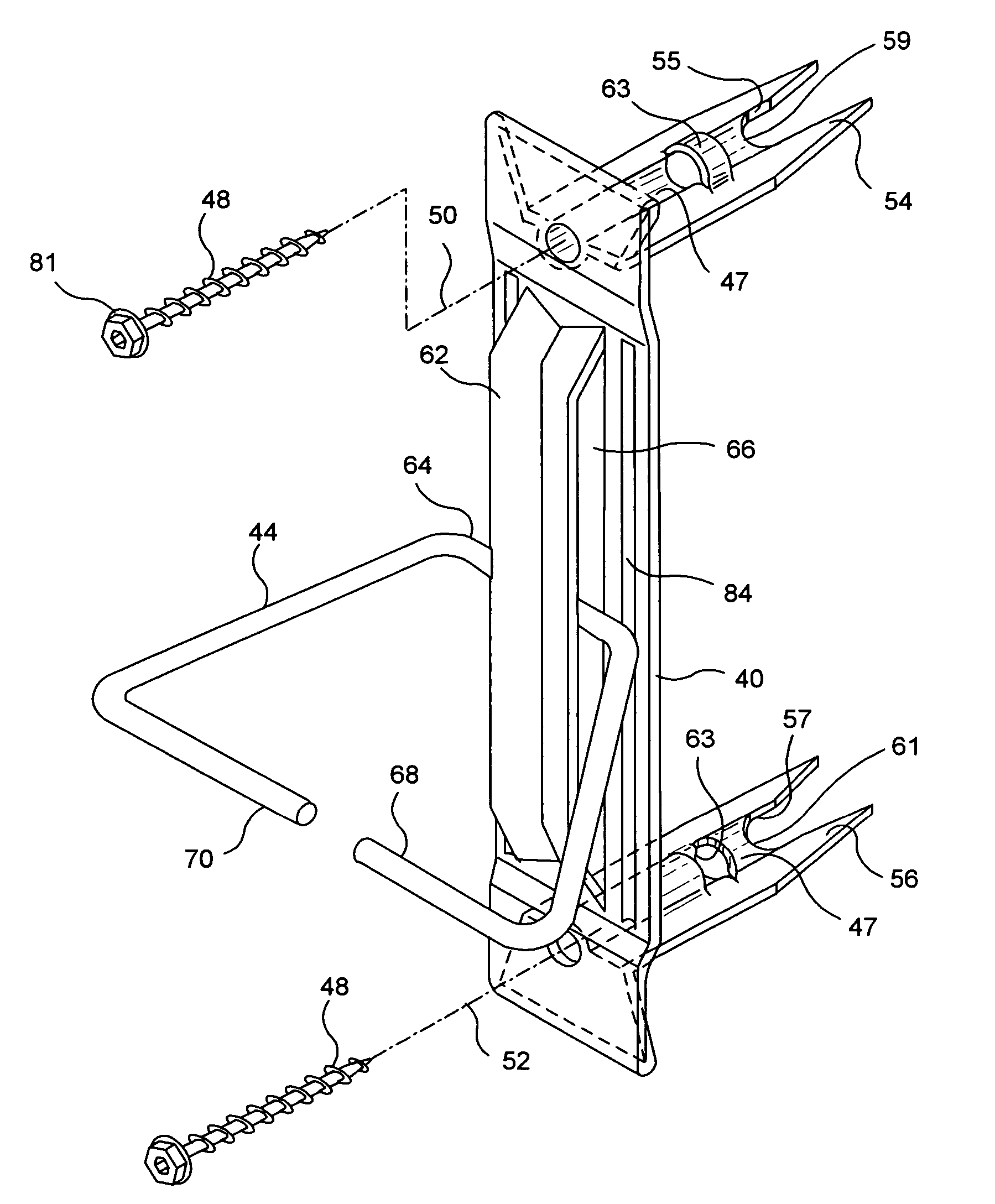
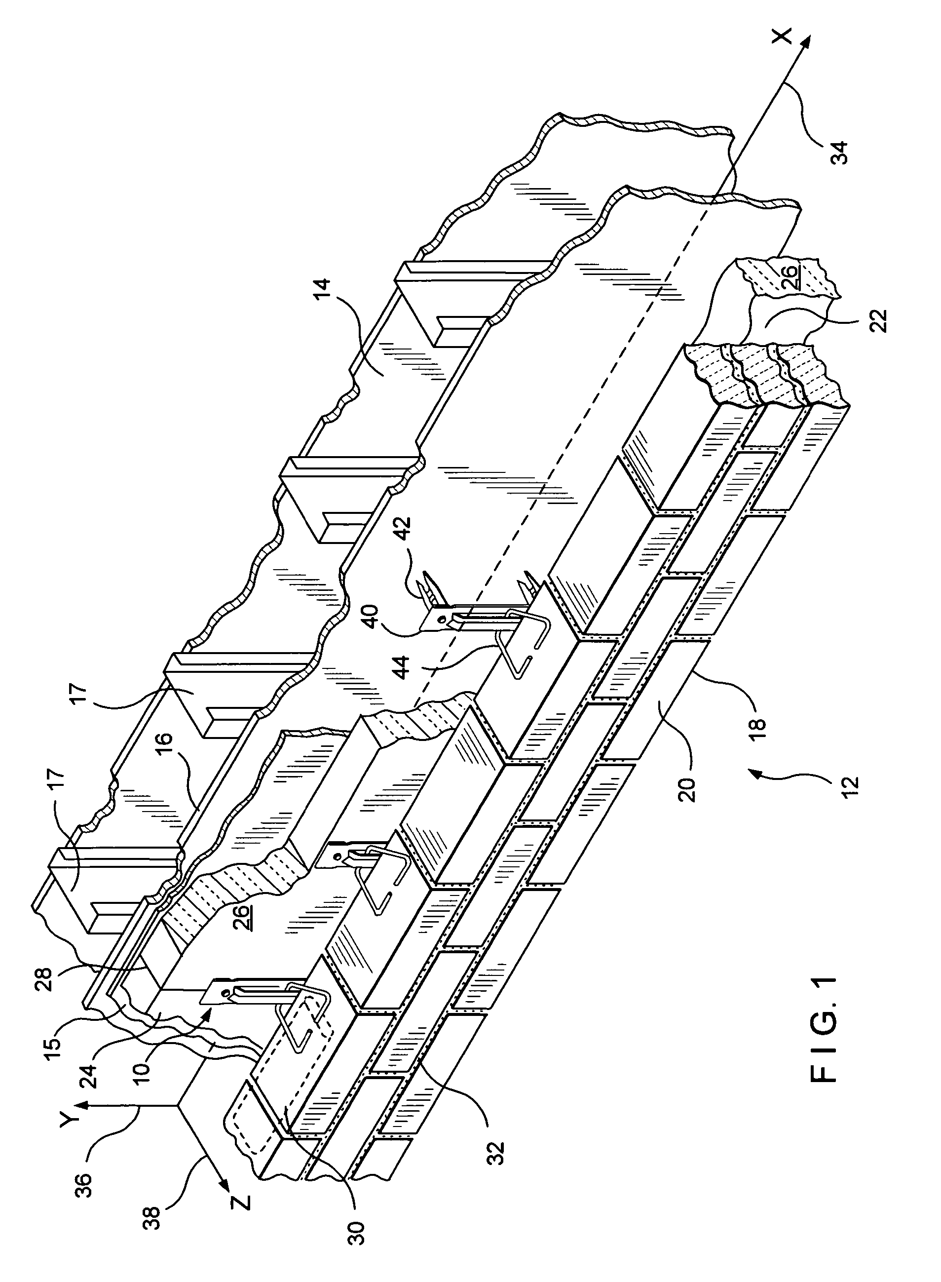
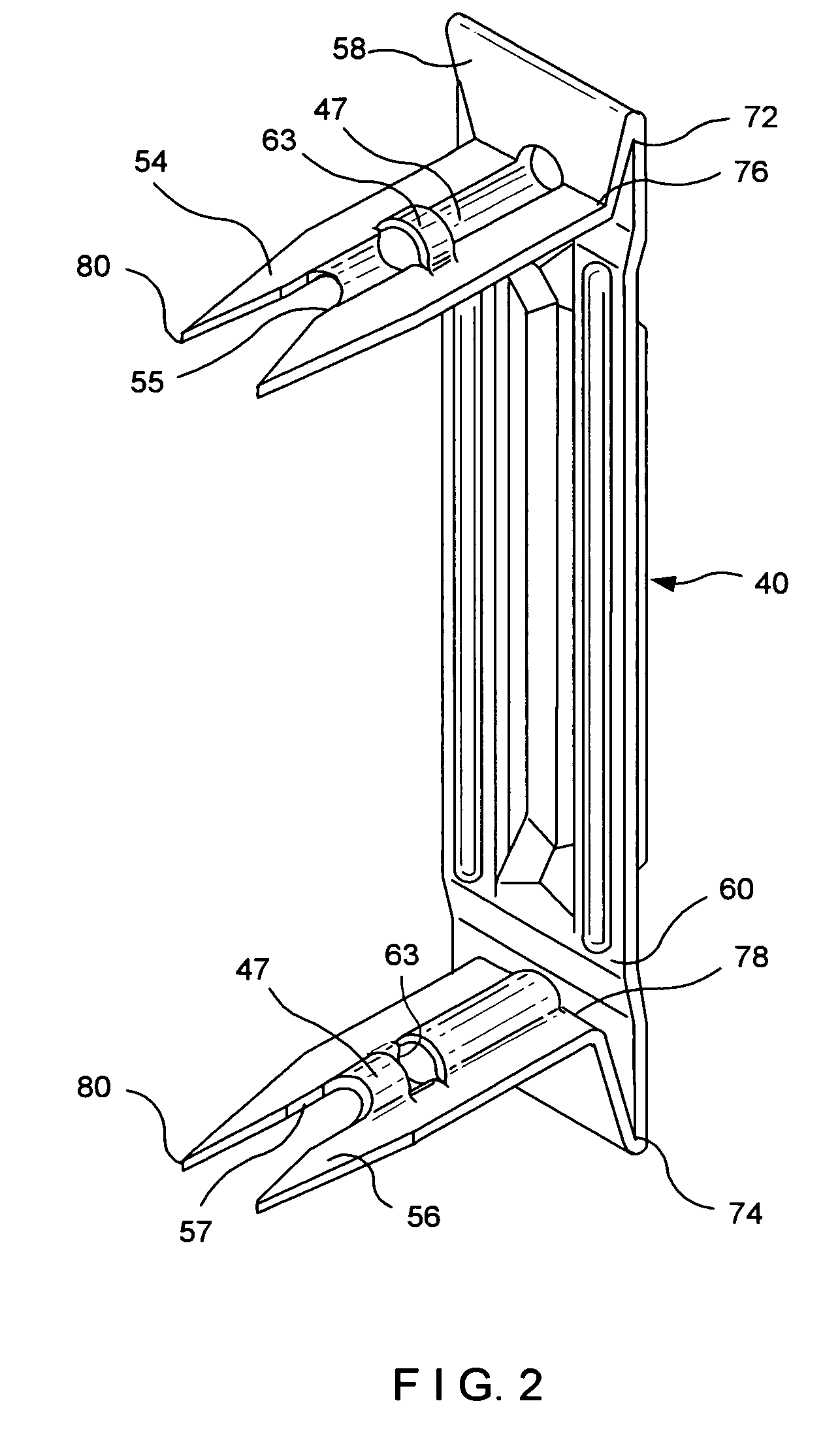
[0089]In this embodiment, as best seen in FIGS. 6 and 7, strengthening ribs 184 are impressed in the base 158 of wall anchor 140. The ribs 184 are substantially parallel to the bail opening 166 and, when mounting hardware 148 is fully seated so that the base 158 surface rests against the face of insulation 126, the ribs 184 are then raised from the surface of the insulation 126. Thus, the ribs 184 are shown as protruding away the insulation, in a manner opposite that of the This alternative structure is particularly applicable where the outer layer of the inner wythe is noncompressible and does not conform to the rib contour. The ribs 184 strengthen the wall anchor 140 and achieves an anchor with a tension and compression rating of 100 lbf.

[0090]The dimensional relationship between wall anchor 140 and veneer tie 144 limits the axial movement of the construct. Each veneer tie 144 has a rear leg 164 opposite the bed-joint deposited portion thereof, which rear leg 164 is formed contin...

third embodiment

[0098]In this third embodiment, slotted wing portions 262 therealong are bent upwardly (when viewing legs 242 as being bent downwardly) from intermediate base 260 for receiving veneer tie 244 therethrough. The dimensional relationship between wall anchor 240 and veneer tie 244 limits the axial or xz-plane movement of the construct. Each veneer tie 244 has a rear leg 264 opposite the bed-joint deposited portion thereof, which rear leg 264 is formed continuous therewith. The slots 266 provide for z-axis 238 limitation and for adjustability along the y-axis 236 movement of the anchored veneer. The opening of the slot 266 of wing portions 262 is constructed to be within the predetermined dimensions to limit the z-axis 238 movement in accordance with the building code requirements. The slots 266 are slightly larger horizontally than the diameter of the tie 244. The dimensional relationship of the rear leg 264 to the width of spacing between wing portions 262 limits the x-axis movement of...


PUM


Abstract

Notched, surface-mounted wall anchors and anchoring systems employing the same are disclosed. The anchor is a notched, folded sheetmetal construct utilizable with various wire formative veneer ties. The depth of the notch is greater than the combined thickness of the wallboard and the waterproofing layer. Various embodiments show wall anchor configurations with suitable veneer ties and differing sheathing arrangements. The notches, upon surface-mounting of the wall anchor, form small wells in the portion of the notch extending into the insulation, which wells entrain water vapor, condensate and water, and relieve the same from being driven into the wallboard.

Description

CROSS-REFERENCES TO RELATED APPLICATIONS[0001]This application is a continuation-in-part of U.S. patent application entitled HIGH-STRENGTH SURFACE-MOUNTED ANCHORS AND WALL ANCHOR SYSTEMS USING THE SAME, Ser. No. 10 / 785,209 filed Feb. 24, 2004, which application is, in turn, a continuation-in-part of U.S. patent application entitled FOLDED WALL ANCHOR AND SURFACE-MOUNTED ANCHORING, Ser. No. 10 / 426,993, filed Apr. 30, 2003, now U.S. Pat. No. 6,925,768.BACKGROUND OF THE INVENTION[0002]1. Field of the Invention[0003]This invention relates to notched wall anchors and to surface-mounted anchoring systems employing the same, both of which are used in cavity wall constructs. More particularly, the invention relates to sheetmetal wall anchors and wire formative veneer ties that comprise positive interlocking components of the anchoring system. The system has application to seismic-resistant structures and to cavity walls having special requirements. The latter include high-strength requireme...

Claims


Application Information

Patent Timeline
Patent Type & Authority Patents(United States)
IPC IPC(8): E04B1/38E04B1/02
CPCE04B1/4178
Inventor HOHMANN, JR., RONALD P.
Owner HOHMANN & BARNARD INC
Why Eureka
Try Eureka