

Tractor intelligent control method and intelligent control system
An intelligent control system and intelligent control technology, applied in mechanical equipment, combustion engines, internal combustion piston engines, etc., can solve problems such as difficult to achieve tractor slip and overload protection, and reduce fuel consumption, reduce slip rate, reduce The effect of the degree of wear
- Summary
- Abstract
- Description
- Claims
- Application Information
AI Technical Summary
Problems solved by technology
Method used
Image

Examples
Embodiment Construction
[0025] The present invention will be described in further detail below in conjunction with the accompanying drawings.
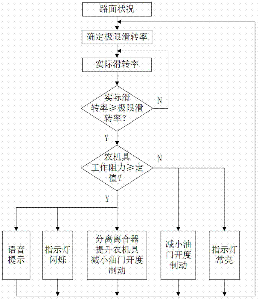
[0026] Such as figure 1 As shown, a tractor intelligent control method, the steps are as follows:
[0027] a) Monitor the road conditions and set the limit slip rate corresponding to the current road conditions;
[0028] b) judging whether the real-time slip rate is less than the limit slip rate corresponding to the current road condition;
[0029] c) If the real-time slip rate is greater than or equal to the limit slip rate corresponding to the current road conditions, further judge whether the tractor is overloaded, if not, reduce the throttle opening and brake; if overloaded, reduce the throttle Open, brake and cut off the power output of the engine to the power system, and lift the agricultural implements.
[0030] When the tractor is in an excessive slipping or overloading state, the above method can relieve the excessive slipping or overloading state...
PUM
 Abstract
Description
Claims
Application Information