
Grinding apparatus having sludge-removing device and method of removing sludge

a technology of sludge removal device and grinding machine, which is applied in the direction of grinding machine components, grinding surface conditioning devices, manufacturing tools, etc., can solve the problems of expensive ultrasonic oscillators and a relatively short life of brushes, and achieve the effect of easy and inexpensive removal

Inactive Publication Date: 2009-07-21
DENSO CORP
View PDF15 Cites 2 Cited by
  • Summary
  • Abstract
  • Description
  • Claims
  • Application Information

AI Technical Summary

Benefits of technology

[0007]The present invention has been made in view of the above-mentioned problems, and an object of the present invention is to provide an improved grinding apparatus, in which sludge accumulated on a grinder is easily and inexpensively removed. Another object of the present invention is to provide an improved method of removing sludge from the grinder.

Problems solved by technology

The brush has a relatively short life because the thin wires easily wear.
In this method, however, an expensive ultrasonic oscillator is required.

Method used


Image

  • Grinding apparatus having sludge-removing device and method of removing sludge
  • Grinding apparatus having sludge-removing device and method of removing sludge
  • Grinding apparatus having sludge-removing device and method of removing sludge

Examples


first embodiment

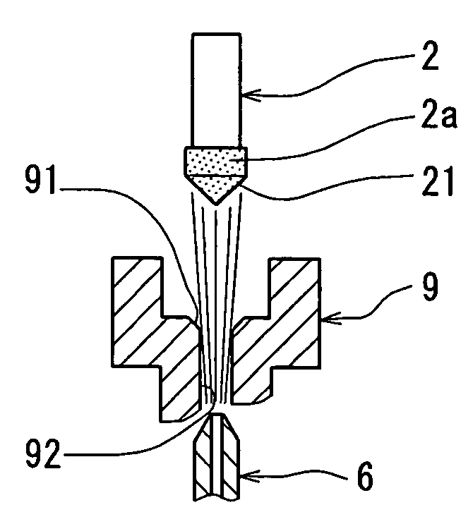
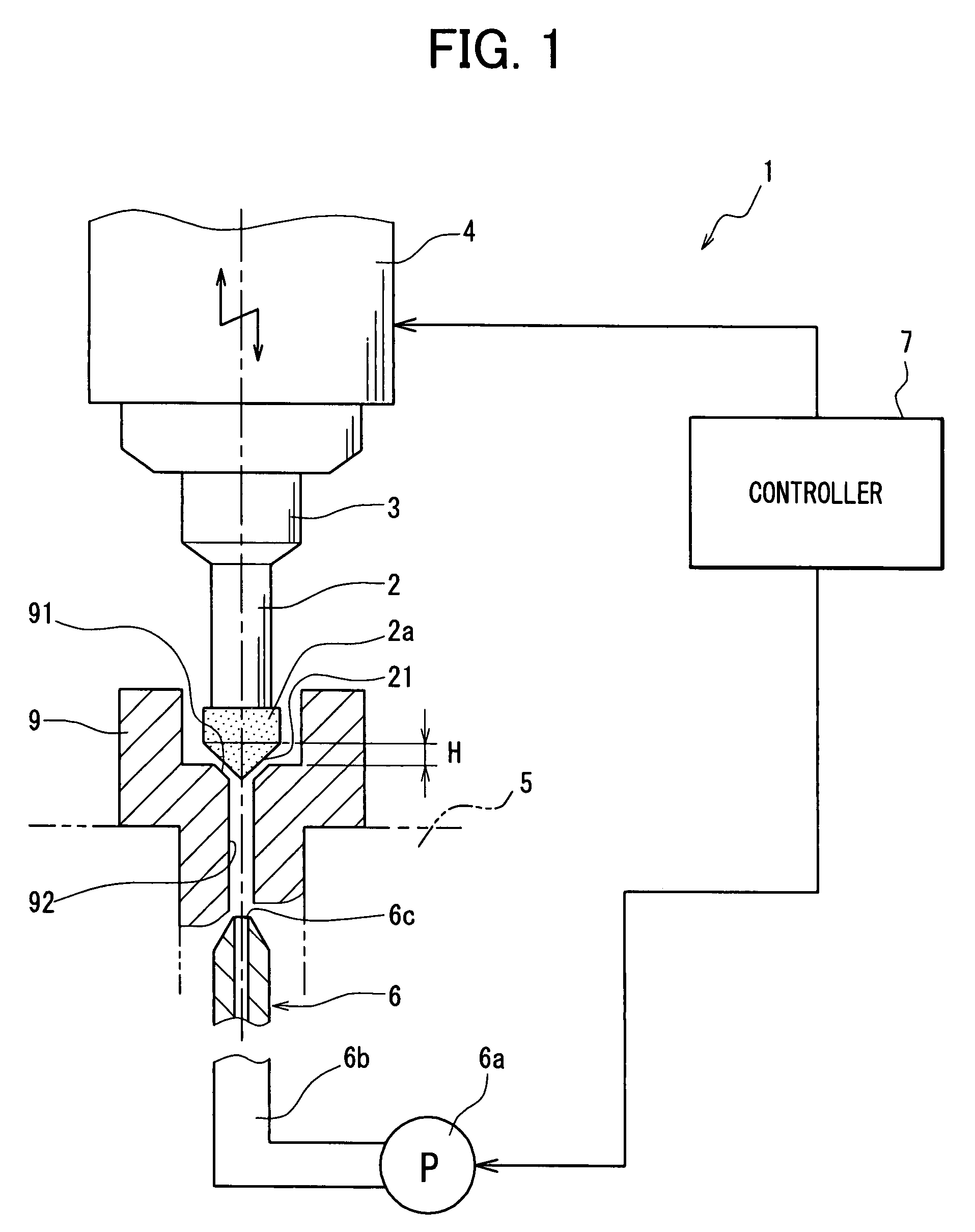
[0018]the present invention will be described with reference to FIGS. 1-4. First, referring to FIG. 1, an entire structure of a grinding apparatus 1 will be described. Though the grinding apparatus 1 is vertically positioned in FIG. 1, it is, of course, possible to position it horizontally. The grinding apparatus 1 is composed of a driving device 4 for driving grinder shaft 2 to which a grinder 2a is connected, a coolant-supplying device 6 including a coolant source 6a and a supply tube 6b, and a controller 7 that controls operation of the driving device 4 and the coolant-supplying device 6. The grinder shaft 2 is chucked by a chuck 3. As the grinder 2, the electrodeposited grinder or the conductive grinder, mentioned above, may be used. In this embodiment, the electrodeposited grinder is used.

[0019]A work 9 having a portion to be ground, which is a tapered surface 91 in this particular embodiment, is held by a holder 5. The grinder 2a has a grinding surface 21, which is a conical s...

second embodiment

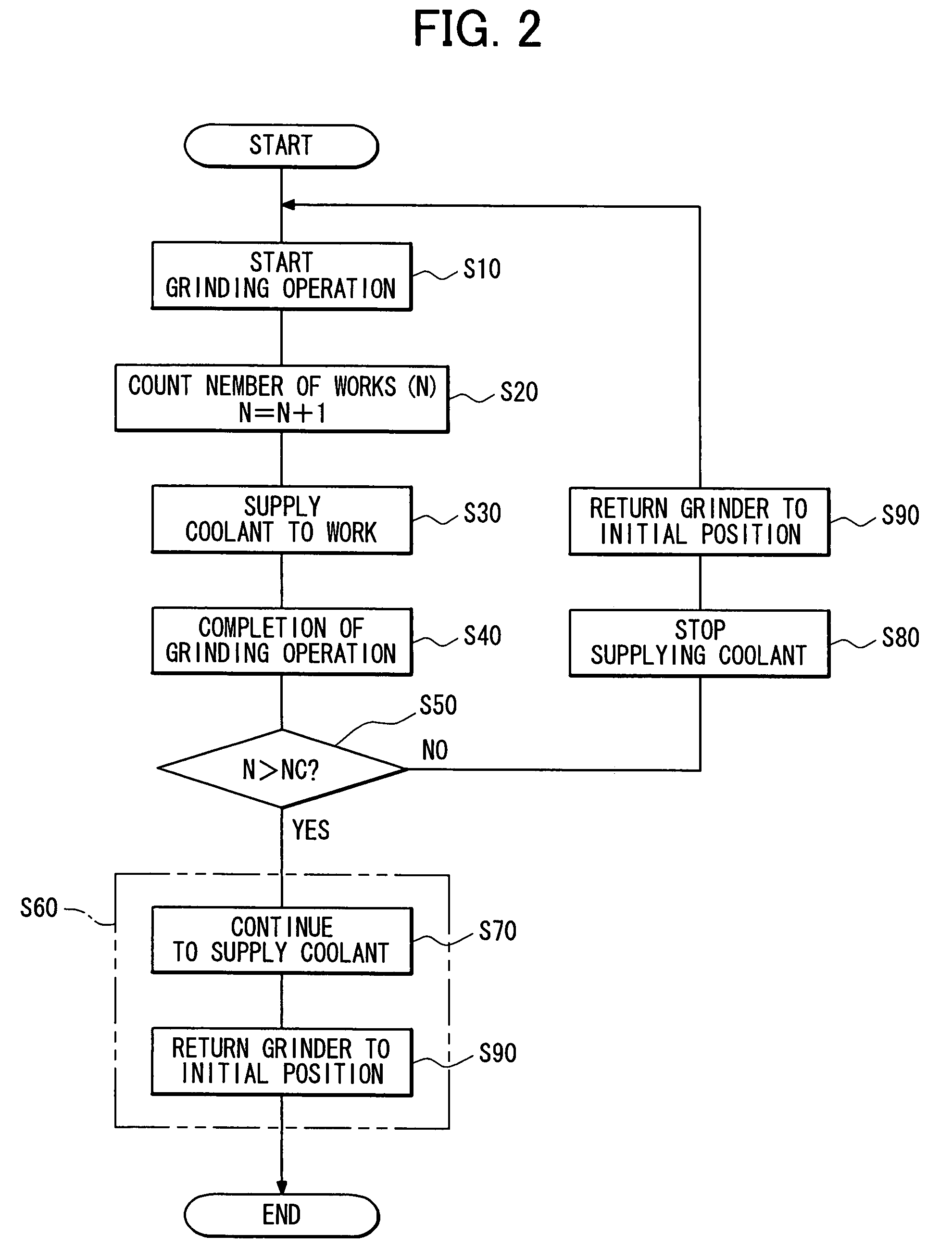
[0032]the present invention will be described with reference to FIG. 5 showing a process of controlling the grinding apparatus 1. In this embodiment, the grinder 2a is cleaned either by a brush device 8 having a brush 8a (shown in FIG. 6B) or by injecting the coolant. At step S120 the number (N) of works 9 that have been ground is counted. At step S150, whether N is larger than a predetermined number NC is determined. If N is larger than NC, the process proceeds to step S60 (the same step as the step S60 shown in FIG. 2), where the sludge on the grinder 2a is removed by injecting the coolant while the grinder 2a is leaving the work 9 and returning to its original position. Preferably, the predetermined number NC in this embodiment is set to 20. If N is smaller than NC, the process proceeds to step S160, where the sludge on the grinding surface 21 is removed by brushing as shown in FIG. 6B. In this cleaning operation, the brush 8a is rotated.

[0033]As described above, the grinder 2a i...


PUM

PropertyMeasurementUnit
pressureaaaaaaaaaa
pressureaaaaaaaaaa
electric-conductiveaaaaaaaaaa

Abstract

A work having a portion to be ground, such as a tapered surface, is ground by a grinder driven by a driving device. During grinding operation, coolant is supplied to a grinding surface of the grinder and the portion to be ground. After the grinding operation is completed, the coolant is continued to be supplied for removing sludge on the grinder while the grinder is leaving the work and returning to its original position. The coolant may be pressurized to a higher level when it is supplied for removing the sludge than when it is supplied during the grinding operation. The number of works that have been already ground may be counted, and the coolant for removing the sludge may be supplied only when the number of works exceeds a predetermined number. Alternatively, the sludge is removed by brushing when the number of works does not reach the predetermined number.

Description

CROSS-REFERENCE TO RELATED APPLICATION[0001]This application is based upon and claims benefit of priority of Japanese Patent Application No. 2006-104613 filed on Apr. 5, 2006, the content of which is incorporated herein by reference.BACKGROUND OF THE INVENTION[0002]1. Field of the Invention[0003]The present invention relates to a grinding apparatus, and more particularly to a sludge-removing device and a method of removing sludge.[0004]2. Description of Related Art[0005]A grinding apparatus, in which grinding operation is performed while supplying coolant to a surface to be ground and a grinder surface, has been known hitherto. Grinders, such as a conductive grinder made by binding grinder particles such as diamond particles with an electric-conductive binder or an electrodeposited grinder made by fixing grinding particles by electrolytic deposition, has been used. Sludge accumulated on the grinder in grinding operation has to be removed to recover sharpness of the grinder.[0006]JP-...

Claims


Application Information

Patent Timeline
Patent Type & Authority Patents(United States)
IPC IPC(8): B24B1/00
CPCB24B9/00B24B15/02B24B55/02B24B53/007B24B33/025
Inventor OOTA, MITSUOYASUDA, TOSHIYUKIYUITOU, MAKOTOKOBAYASHI, KOUICHI
Owner DENSO CORP
Learn More