
Substrate transportation method and apparatus

Inactive Publication Date: 2007-12-06
VISTA PEAK VENTURES LLC
View PDF6 Cites 2 Cited by
  • Summary
  • Abstract
  • Description
  • Claims
  • Application Information

AI Technical Summary

Benefits of technology

[0009]In view of the above problems associated with prior art, it is an object of the present invention to provide a relatively simple, compact and less expensive substrate transportation method and apparatus that is capable of effectively removing dust or any other foreign materials attached to the bottom surface of the substrate under transportation, thereby improving productivity and performance of the electronic device fabricated by employing such substrate. It is to be noted that the term “substrate” means in this specification any thin plate member preferably used for, but not limited to, fabrication of electronic devices.
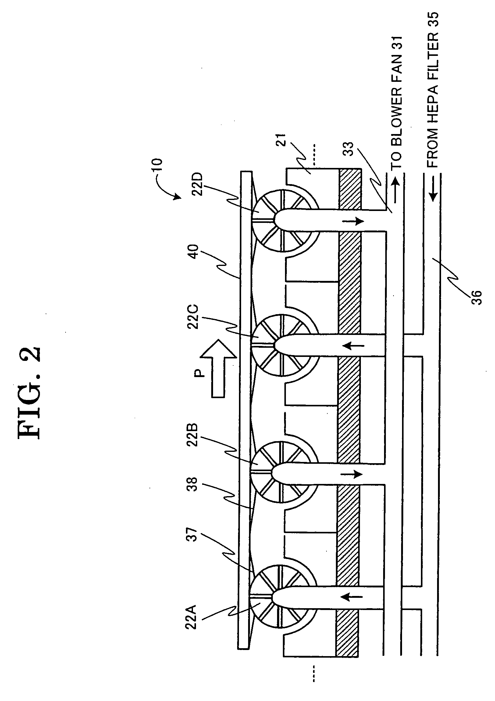
[0019]The substrate transportation method and apparatus according to the present invention exhibit the following practical advantages. Since transportation rollers in the substrate transportation section are provided with an air blowing / sucking portion integrally with the transportation rollers for blowing and sucking gas (e.g., air), it is possible to effectively remove dust or any other foreign materials from the substrate surface with relatively simple, compact and less expensive construction. Moreover, since slit nozzles are formed with a plurality of transportation rollers disposed in plural rows at a constant distance in the substrate transporting direction for alternately blowing and sucking gas, dust or any other foreign materials blown by the air-flow from slit nozzles in a staggered configuration in one transportation roller is sucked in the immediately adjacent transportation rollers, thereby effectively removing dust or any other foreign materials on the substrate surface.
[0020]Additionally, the use of discharging and intake gases in blowing and sucking tubes from a common blower fan enables to easily and inexpensively remove dust or any other foreign materials from the substrate surface. It is also possible that the filter in the air-blow tube prevents dust in the circulating gas (e.g., air) from reattaching to the substrate surface. Since each transportation roller is designed to continuously change its diameter in the width direction of the substrate under transportation, the contacting area with the substrate surface is minimized, thereby minimizing the possibility of collecting dust or any other foreign materials on the substrate surface.

Problems solved by technology

In such electronic devices, attachment of dust or any other foreign materials on the surface of such substrate results in defective pixels or semiconductor devices for driving such pixels, thereby determining quality, production yield (or productivity), production cost and the like of the fabricated electronic device.
However, such conventional technologies as described hereinabove require relatively complicated, bulky and expensive apparatus for removing dust or any other foreign materials from the bottom surface of the substrate.
It is also difficult to effectively remove foreign materials from the substrate under transportation.

Method used


Image

  • Substrate transportation method and apparatus
  • Substrate transportation method and apparatus
  • Substrate transportation method and apparatus

Examples


Embodiment Construction

[0024]Now, the construction and operation of a preferred embodiment of the substrate transportation method and apparatus according to the present invention will be described in detail with reference to the accompanying drawings.

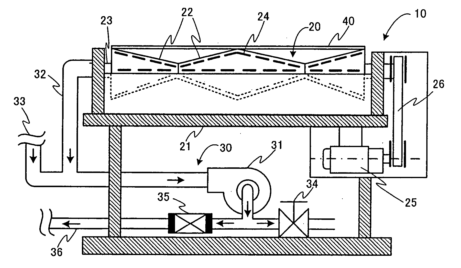
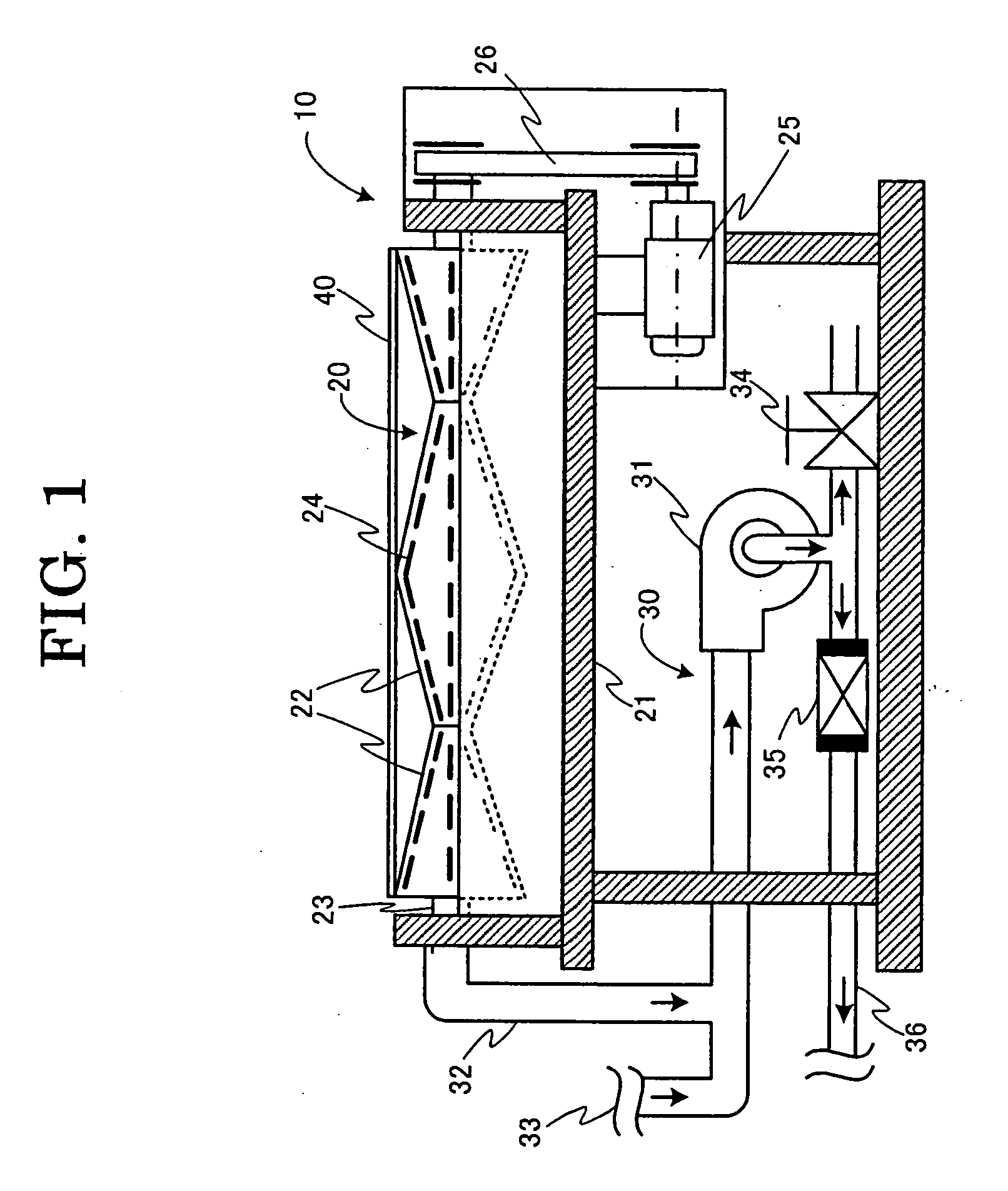
[0025]Firstly, a reference is made with FIG. 1 illustrating the partially cross section side view of a preferred embodiment of the substrate transportation apparatus according to the present invention. The substrate transportation apparatus 10 comprises primarily a substrate transportation section 20 and a gas blowing / sucking section (referred to as an air blowing / sucking section below) 30. As will be described hereinafter in detail, a substrate 40, i.e., a thin plate member such as a glass substrate or the like is transported in the direction vertical to the sheet of FIG. 1.

[0026]The substrate transportation section 20 comprises a plurality of transportation rollers 22 through which respective rotary shafts 23 extend. Each rotary shaft 23 extends through bot...


PUM


Abstract

The substrate transportation apparatus 10 comprises a plurality of transportation rollers 22A-22D disposed at a predetermined spacing for transporting the substrate 40 in response to rotation of the transportation rollers 22. Each of the transportation rollers 22 is generally hollow cylindrical member formed with a plurality of slit nozzles 24 in the circumference. Alternating rows of the transportation rollers 22 are designed to blow and suck air to and from the bottom surface of the substrate 40 under transportation while preventing dust or any other foreign materials from collecting on the bottom surface of the substrate 40.

Description

BACKGROUND OF THE INVENTION[0001]This application claims benefits of Japanese Patent Application No. 2006-137412 filed on May 17, 2006, the contents of which are incorporated by the references.[0002]The present invention relates to a substrate transportation method and apparatus, more specifically to a method and an apparatus for transporting a substrate such as a glass plate to be used in fabrication of an electronic device such as a liquid crystal display panel (LCD), a semiconductor integrated device (IC) or the like from one location to another while removing dust or any other foreign materials attached to or collected on the back surface of such substrate.[0003]Electronic devices such as color liquid crystal display panels or the like are generally fabricated through a series of fabrication steps such as masking, photo lithography, etching, bonding and the like for fabricating on the front surface of such substrate semiconductor devices that drive pixels of such display devices...

Claims


Application Information

Patent Timeline
IPC IPC(8): H01L21/00
CPCH01L21/67784
Inventor NAGATOMO, KAZUYA
Owner VISTA PEAK VENTURES LLC
Learn More