Compact waveguide antenna array and feed

Active Publication Date: 2009-07-21
L3 TECH INC
View PDF9 Cites 72 Cited by
  • Summary
  • Abstract
  • Description
  • Claims
  • Application Information

AI Technical Summary

Benefits of technology

[0006]It has been recognized that it would be advantag

Problems solved by technology

Simple antennas, however, are generally limited in terms of performance, providing limited gain/directivity and shaping of the radiation pattern.
At microwave frequencies, antenna feed design can be difficult when small element-to-element spacing relative to the wavelength is desired and potential for high losses.
These bends and twists take up large amounts of space, ho

Method used


Image

  • Compact waveguide antenna array and feed
  • Compact waveguide antenna array and feed
  • Compact waveguide antenna array and feed

Examples


Embodiment Construction

[0020]Reference will now be made to the exemplary embodiments illustrated in the drawings, and specific language will be used herein to describe the same. It will nevertheless be understood that no limitation of the scope of the invention is thereby intended. Alterations and further modifications of the inventive features illustrated herein, and additional applications of the principles of the inventions as illustrated herein, which would occur to one skilled in the relevant art and having possession of this disclosure, are to be considered within the scope of the invention.

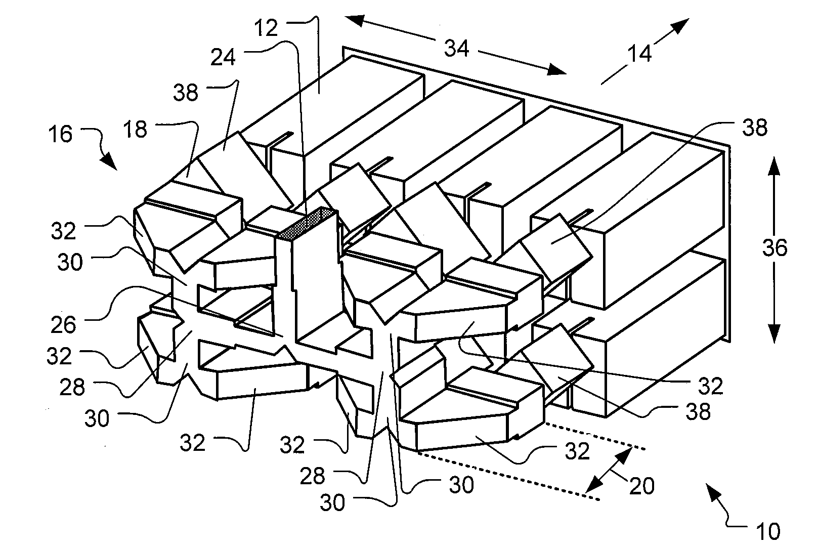
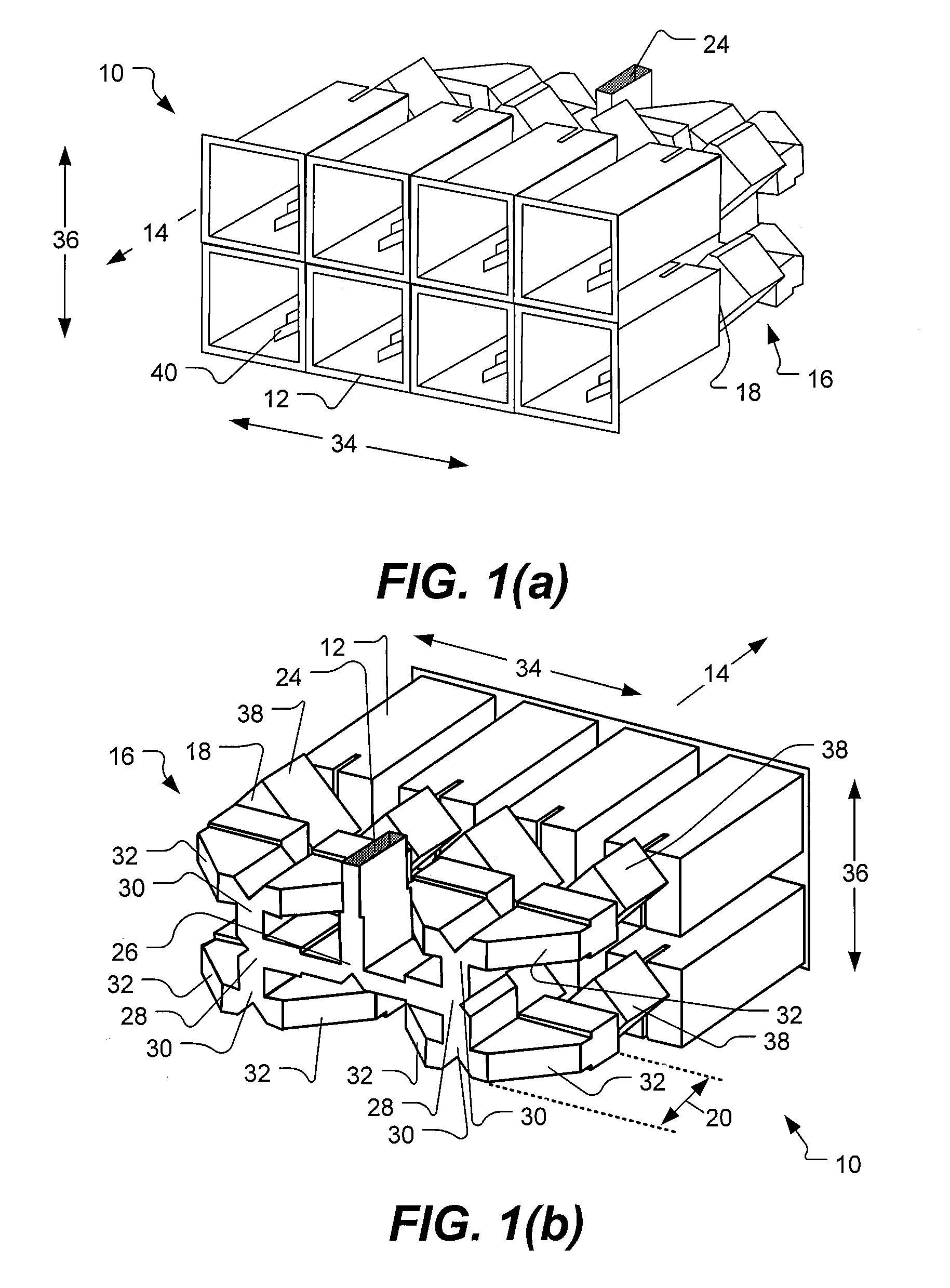
[0021]FIGS. 1(a) and 1(b) provide a perspective illustration of an antenna array in accordance with a first embodiment of the present invention. The antenna array, shown generally at 10, includes eight horn antenna elements 12. The horn antenna elements are arranged in a plane with the open faces facing in the radiation direction 14 and defining an array surface. The horn antenna elements can include a septum pol...


PUM


Abstract

A compact waveguide antenna array feed system provides antenna element ports spaced along an array face by less than one free-space wavelength in at least one dimension, while retaining a thickness in a direction perpendicular to the array face of less than one and one-half free-space wavelength.

Description

FIELD OF THE INVENTION[0001]The present invention relates generally to waveguide antenna feeds and array antennas.BACKGROUND[0002]Antennas provide for the radiation or reception of electromagnetic signals. An antenna may be characterized in terms of gain, beamwidth, or more specifically in terms of the antenna pattern which is a measure of the antenna gain as a function of direction. Simple antennas, such as dipoles or horns are well known, and find use in a number of applications. Simple antennas, however, are generally limited in terms of performance, providing limited gain / directivity and shaping of the radiation pattern.[0003]Antenna arrays use a number of simple antenna elements to provide increased gain and directivity over what can be achieved using a single antenna element. In reception, signals from the individual elements are combined with appropriate phases and weighted amplitudes to provide the desired antenna pattern. Antenna arrays are also used in transmission, splitt...

Claims


Application Information

Patent Timeline
IPC IPC(8): H01Q13/00
CPCH01Q13/0241H01Q21/064H01Q21/0087B33Y80/00
Inventor EDWARDS, RICHARD GERALDSORENSEN, RORY KIMBUCHANAN, ALAN MCLEAN
Owner L3 TECH INC
Why Eureka
Try Eureka