
Apparatus and method for raster tile coalescing

a technology of raster tile and coalescing method, applied in the field of raster tile coalescing method, can solve the problems of inefficient memory access operation, inability to organize memory accesses with a high degree of memory coherency, and the comparatively large amount of processing resources for pixel shading. to achieve the effect of improving the transaction coherency of downstream processing elements

Active Publication Date: 2009-07-21
NVIDIA CORP
View PDF4 Cites 24 Cited by
  • Summary
  • Abstract
  • Description
  • Claims
  • Application Information

AI Technical Summary

Benefits of technology

The patent describes a system that takes groups of pixels and combines them into larger tiles for use in checking for hazards and improving processing in downstream elements. This helps to make the processing more efficient and effective.

Problems solved by technology

Pixel shading typically requires a comparatively large amount of processing resources.
Moreover, pixel shading typically requires memory accesses to access and manipulate data.
The memory access operations may be inefficient unless there is a high degree of memory coherency.
However, in some pixel shader architectures the stream-like manner in which pixel quads are processed makes it difficult to organize memory accesses with a high degree of memory coherency.

Method used


Image

  • Apparatus and method for raster tile coalescing
  • Apparatus and method for raster tile coalescing
  • Apparatus and method for raster tile coalescing

Examples


Embodiment Construction

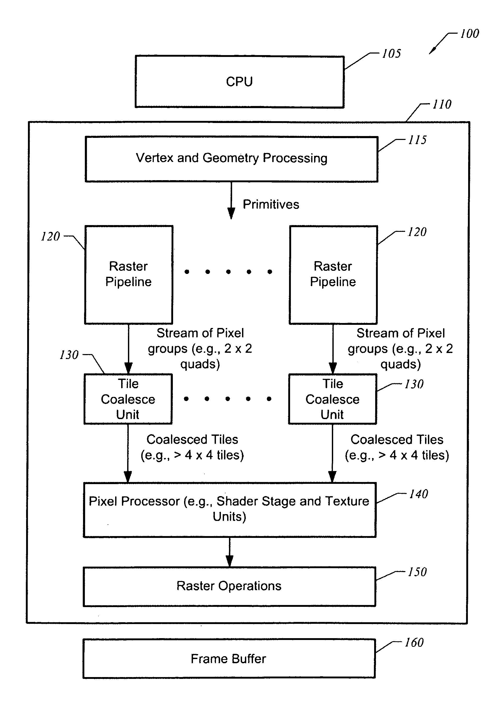
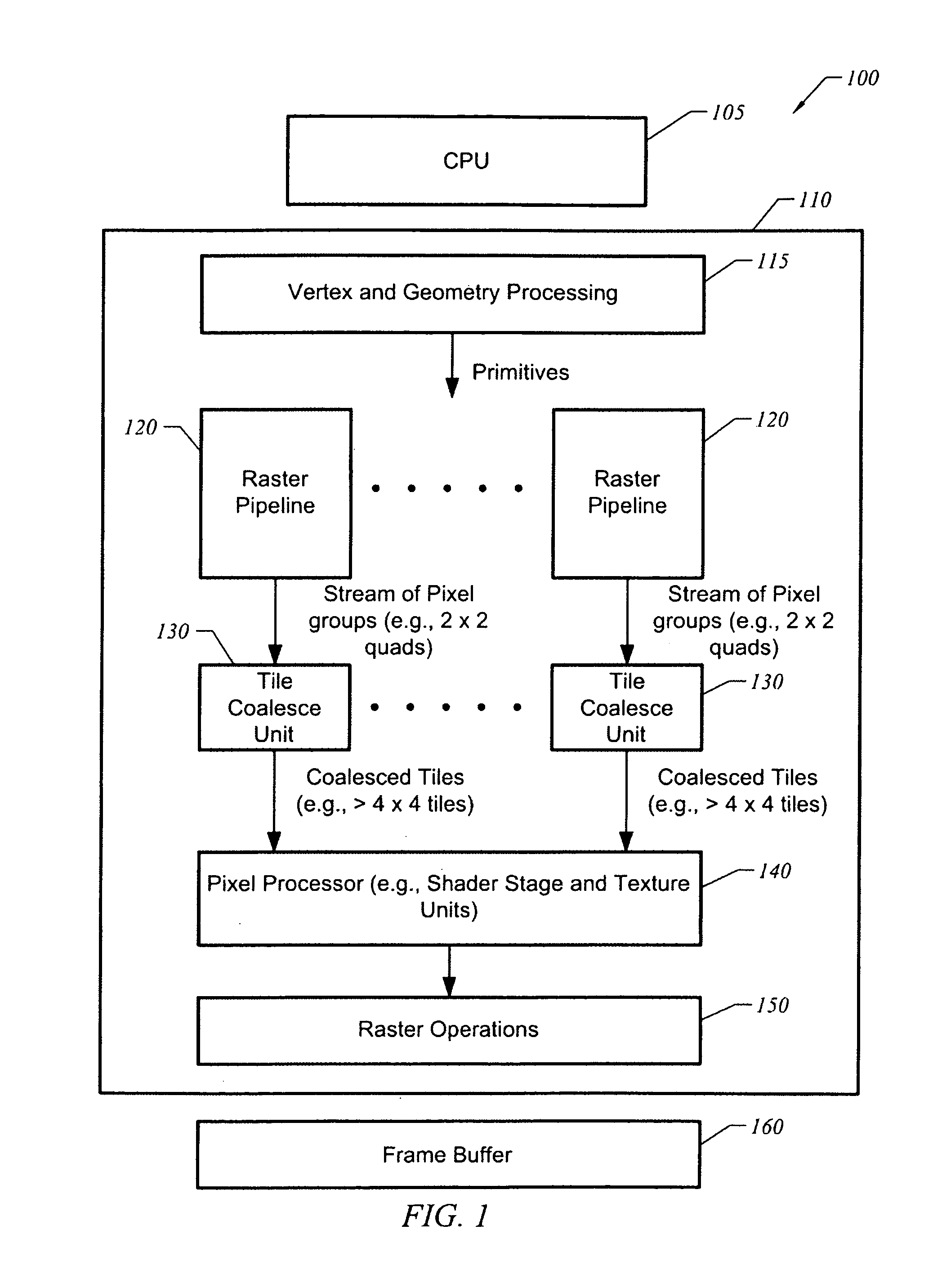
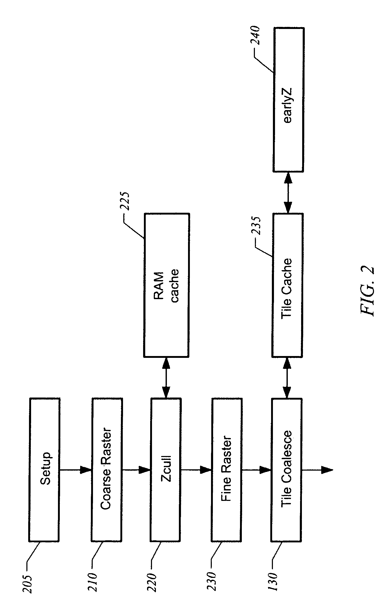
[0015]FIG. 1 is a block diagram of a graphics system 100 in accordance with one embodiment of the present invention. A central processing unit (CPU) 105 generates graphics commands received by a graphics processing unit (GPU) 110. GPU 110 includes a graphics pipeline having at least one stage 115 to perform vertex and geometry processing to generate graphical primitives, such as triangles. The graphics pipeline includes at least one raster pipeline 120 to rasterize primitives. As illustrated in FIG. 1, in one embodiment there is a sequence of parallel raster pipelines to rasterize different sections of a screen space in parallel. Each raster pipeline outputs data as a stream of pixel groups of a pre-selected size, such as 2×2 quads of pixels covering four pixels. For example, each raster pipeline 120 outputs a first quad, a second quad, and so on for a frame. Note that the sequence of parallel raster pipelines may be dedicated to processing specific portions of a screen. Alternative...


PUM


Abstract

A graphics pipeline rasterizes primitives and generates a stream of groups of pixels, such as a stream of pixel quads. A tile coalesce unit received the stream of groups of pixels and generates pixel tiles for use by downstream pixel processing units. The pixel tiles facilitate hazard checks and transaction coherency.

Description

FIELD OF THE INVENTION[0001]The present invention is generally related to techniques to improve memory coherency and perform hazard checking in pixel processors.BACKGROUND OF THE INVENTION[0002]A Graphics Processing Unit (GPU) is typically implemented as a graphics pipeline. Conventionally, one or more stages perform vertex and geometry processing to generate graphical primitives mapped to a two-dimensional screen space. The graphical primitives are typically triangles, although other primitive shapes may also be used. A setup stage is typically included to calculate the edges of graphical primitives (e.g., triangles) and perform other calculations to prepare the primitives for rasterization. A raster stage rasterizes the primitives by determining the coverage of the primitives across sample locations of pixels and generating a set of fragments and pixel locations. Conventionally, the fragments are provided to downstream components as stream of pixels, typically in groups of four pi...

Claims


Application Information

Patent Timeline
Patent Type & Authority Patents(United States)
IPC IPC(8): G06F17/00G06T15/50G09G5/00
CPCG06T11/40G06T15/005G09G2360/122
Inventor LINDHOLM, JOHN ERIKMORETON, HENRY PACKARDMONTRYM, JOHN S.WHITMAN, SCOTT R.
Owner NVIDIA CORP
Learn More