Food pressure-cooking device with a rotary locking/unlocking control device

a control device and food pressure technology, applied in the direction of baking ovens, transportation and packaging, etc., can solve the problems of insufficient ergonomics, insufficient safety in use, and inability to control the movement of the jaws in the prior art, so as to reduce the force the effect of user delivery and compactness

Active Publication Date: 2009-07-28
SEB SA
View PDF10 Cites 77 Cited by
  • Summary
  • Abstract
  • Description
  • Claims
  • Application Information

AI Technical Summary

Benefits of technology

[0013]Consequently, the invention seeks to remedy the various drawbacks listed above and to propose a novel appliance for cooking food under pressure in which the device for controlling the movement of the jaws can be controlled by actions that differ considerably for the operations of closing and of opening, and also enabling the amount of force that a user needs to deliver to be reduced when locking / unlocking the appliance, and also providing a cooking appliance that is more compact.
[0015]Another object of the invention is to propose a cooking appliance that is of simplified design and that is easier to assemble.

Problems solved by technology

It turns out that the device implemented in the prior art for controlling movement of the jaws provides insufficient safety in use and is not sufficiently ergonomic.
Using a rotary knob is ergonomically awkward since it can lead to risks in terms of safety.
The difference between the direction of rotation is generally not sufficient to enable the user to remember in instinctive and natural manner which turning direction corresponds to which technical result (closing or opening).
In the present case, the distinction is made more difficult to establish in that the jaws are hidden by a casing, such that the user cannot see the result of taking action on the rotary knob.
The control operations to be performed are thus relatively constraining, and run the risk of the user putting a hand on a hot portion of the appliance.
It should also be observed that the proposed control mechanism and the relative displacements of the parts made up the control device require the user to impart a relatively large amount of control force, and that too goes against safety in use, since exerting such a large force on the rotary knob increases the risk of the entire pressure cooker escaping from the user's hands, which can be particularly dangerous when the receptacle is hot.
Finally, the prior art appliance is of relatively complex design, making use of numerous moving parts, leading to significant risks of wear and of seizing, and also to high manufacturing costs, for operating reliability that is not optimized.

Method used


Image

  • Food pressure-cooking device with a rotary locking/unlocking control device
  • Food pressure-cooking device with a rotary locking/unlocking control device
  • Food pressure-cooking device with a rotary locking/unlocking control device

Examples


Embodiment Construction

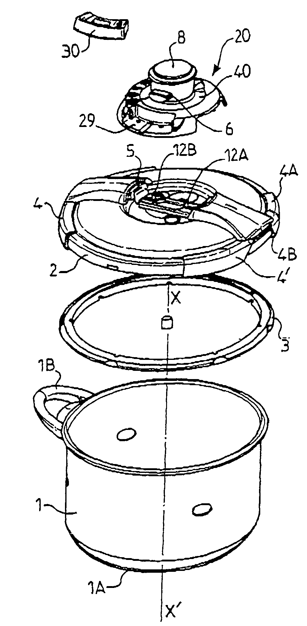
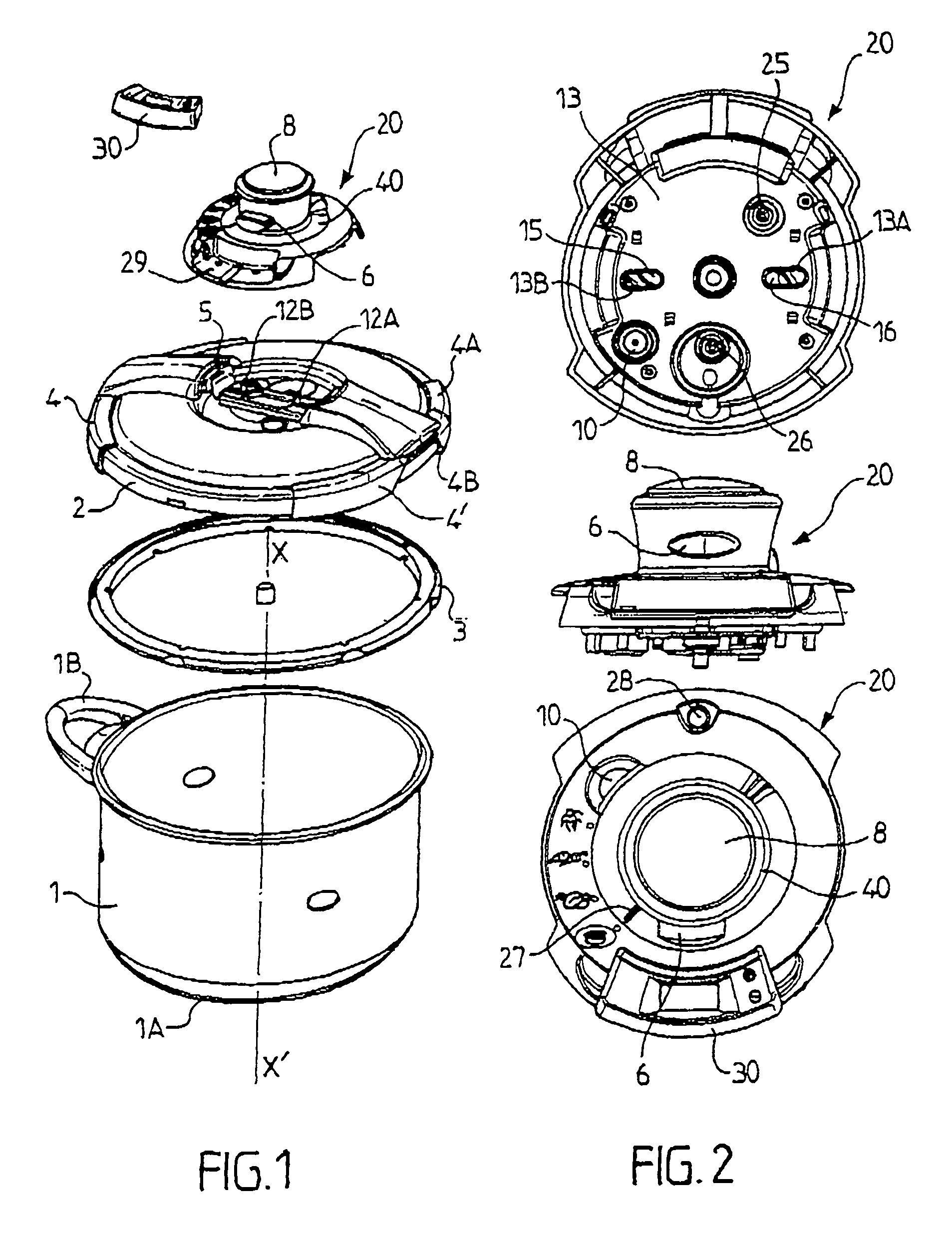
[0033]The cooking appliance in accordance with the invention is for cooking various foods under pressure in a domestic context.

[0034]The cooking appliance comprises a vessel 1 of substantially cylindrical shape having an axis of (circular) symmetry X-X′, and is designed to have a lid 2 fitted thereon in leaktight manner.

[0035]Below, the adjective “axial” is used to refer to the direction of said axis of symmetry, which is close to the vertical when the pressure cooker is in normal operation.

[0036]Conventionally, the vessel 1 is made of a metal material such as stainless steel and it is provided with a heat-conductive bottom 1A that is secured to the vessel 1, e.g. by hot stamping.

[0037]The vessel 1 also includes handle members such as handles 1B fixed to the walls of the vessel 1.

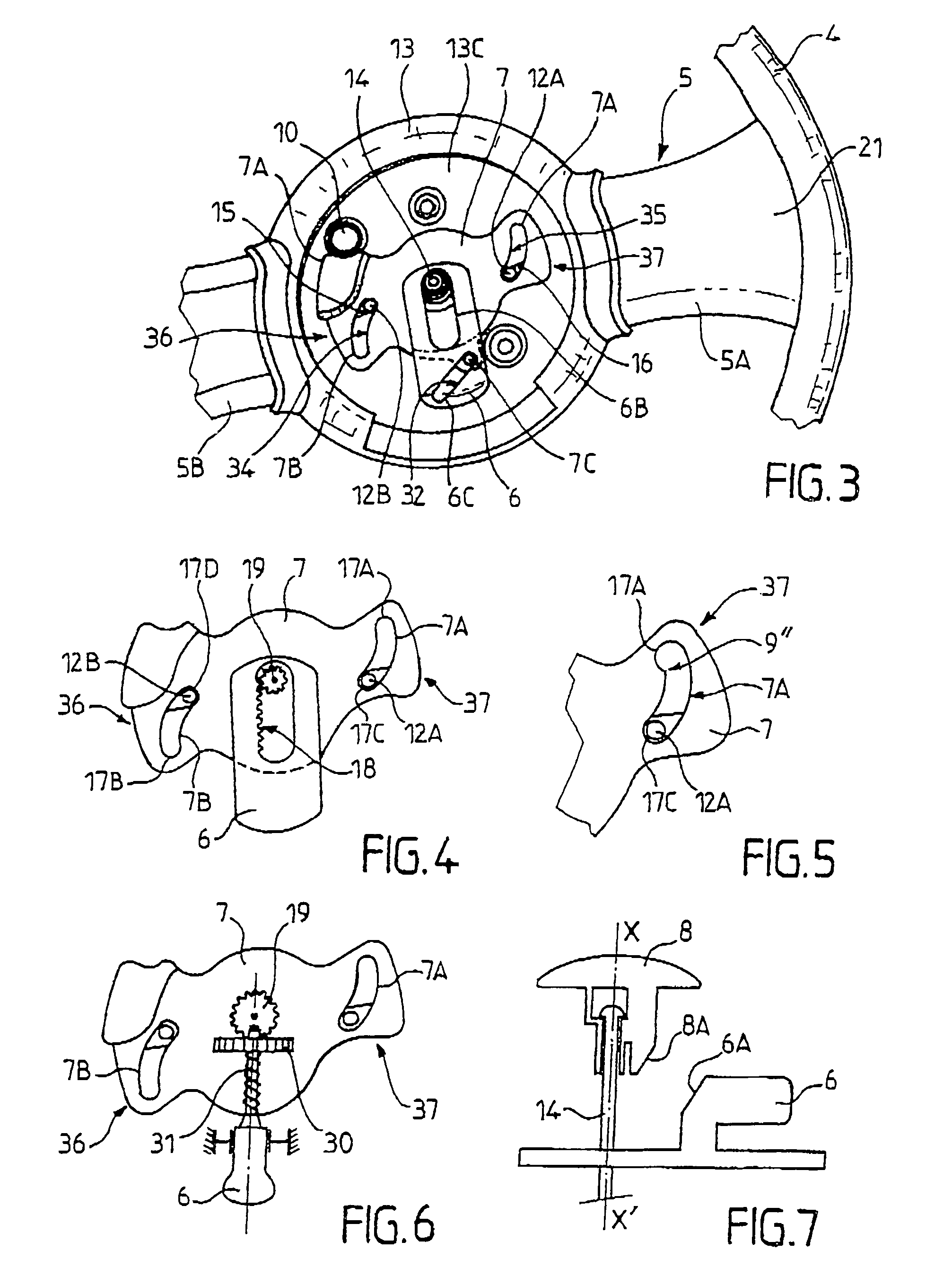
[0038]The lid 2 is generally disk-shaped, and it is locked on the vessel 1 by means of at least one jaw 4 that is mounted to move between a locking position in which the lid is secured to the vessel, and an...


PUM


Abstract

Appliances for cooking food under pressure are disclosed herein. According to one embodiment, a cooking appliance comprises a vessel (1), a lid (2), at least one jaw (4) mounted to be moved by a driving device (5), and an opening / closing control device (6, 7, 8). The opening / closing control device (6, 7, 8) includes an intermediate part (7), which comprises a maneuvering device (7A, 7B) and a clutch device (7C, 19). The intermediate part (7) is mounted to turn freely so that the maneuvering device (7A, 7B) co-operates with the driving device (5). The opening / closing control device also includes a main control member (6) comprising a transmission device (6C), the main control member (6) being positioned so that the transmission device (6C) co-operates with the clutch device (7C). The main control member (6) is mounted to move in translation. Other embodiments disclosed herein are also applicable to domestic appliances for cooking food under pressure.

Description

CROSS-REFERENCE TO RELATED APPLICATIONS[0001]This application is a national stage application of International Application No. PCT / FR03 / 00755, filed Mar. 10, 2003, which claims priority to FR 02 / 03091, filed Mar. 8, 2002, both applications of which are hereby incorporated by reference in their entirety into the present application.TECHNICAL FIELD[0002]The present invention relates to the general technical field of domestic appliances for cooking under pressure that comprise a vessel and a lid designed to be locked on the vessel to form a sealed cooking enclosure, said appliances being intended to cook food contained in the vessel under steam pressure.[0003]The present invention relates to an appliance of the pressure cooker type for cooking food under pressure, and comprising at least:[0004]a vessel and a lid for being fitted to and locked on said vessel in order to form a leaktight cooking enclosure;[0005]one or more jaws mounted to move in translation by drive means between a posi...

Claims


Application Information

Patent Timeline
Patent Type & Authority Patents(United States)
IPC IPC(8): A23L1/00A47J27/08
CPCA47J27/0813Y10S220/912A47J27/08
Inventor CARTIGNY, MICHEL PIERRECHAMEROY, ERIC
Owner SEB SA
Why Eureka
Try Eureka