Fundus observation device, fundus image display device and fundus observation program

a technology of fundus and image, applied in the field of fundus observation device, fundus image display device and fundus observation program, can solve the problems of difficult to capture the detailed state of the fundus surface or the entire retina in detail, difficult to capture the state of the attention area in detail, and difficult to capture the state of the deep layer tissues in detail. achieve the effect of easy to capture the position of the tomographic imag

Active Publication Date: 2009-07-28
KK TOPCON
View PDF7 Cites 35 Cited by
  • Summary
  • Abstract
  • Description
  • Claims
  • Application Information

AI Technical Summary

Benefits of technology

[0046]According to the present invention, as it is configured in a manner such that the 2-dimensional image formed by a first image forming means and the tomographic image formed by a second image forming means are to be displayed in parallel, and at the same time, the cross-sectional position information indicating the cross-sectional position of the tomographic image of the surface of a fundus oculi is displayed so as to be overlapped with the 2-dimensional image, the examiner can easily capture the position of the tomographic image on the 2-dimensional image at a glance, and therefore, the positional relation of the 2-dimensional image and the tomographic image to each other may easily be captured.

Problems solved by technology

However, by just observing an image of the fundus surface obtained from a fundus camera, it is difficult to capture the state of the deep layer tissues in detail, while, with tomographic images of the fundus oculi obtained from an optical image measuring device, it was difficult to capture the detailed state of the fundus surface or the entire retina.
However, with the conventional fundus observation device, it was difficult to capture the state of the attention area in detail, as the positional relation to each other between a 2-dimensional surface image of the fundus of an eye to be examined by a fundus camera and a tomographic image of the fundus by an optical image measuring device was not easy to capture.

Method used


Image

  • Fundus observation device, fundus image display device and fundus observation program
  • Fundus observation device, fundus image display device and fundus observation program
  • Fundus observation device, fundus image display device and fundus observation program

Examples


embodiment 1

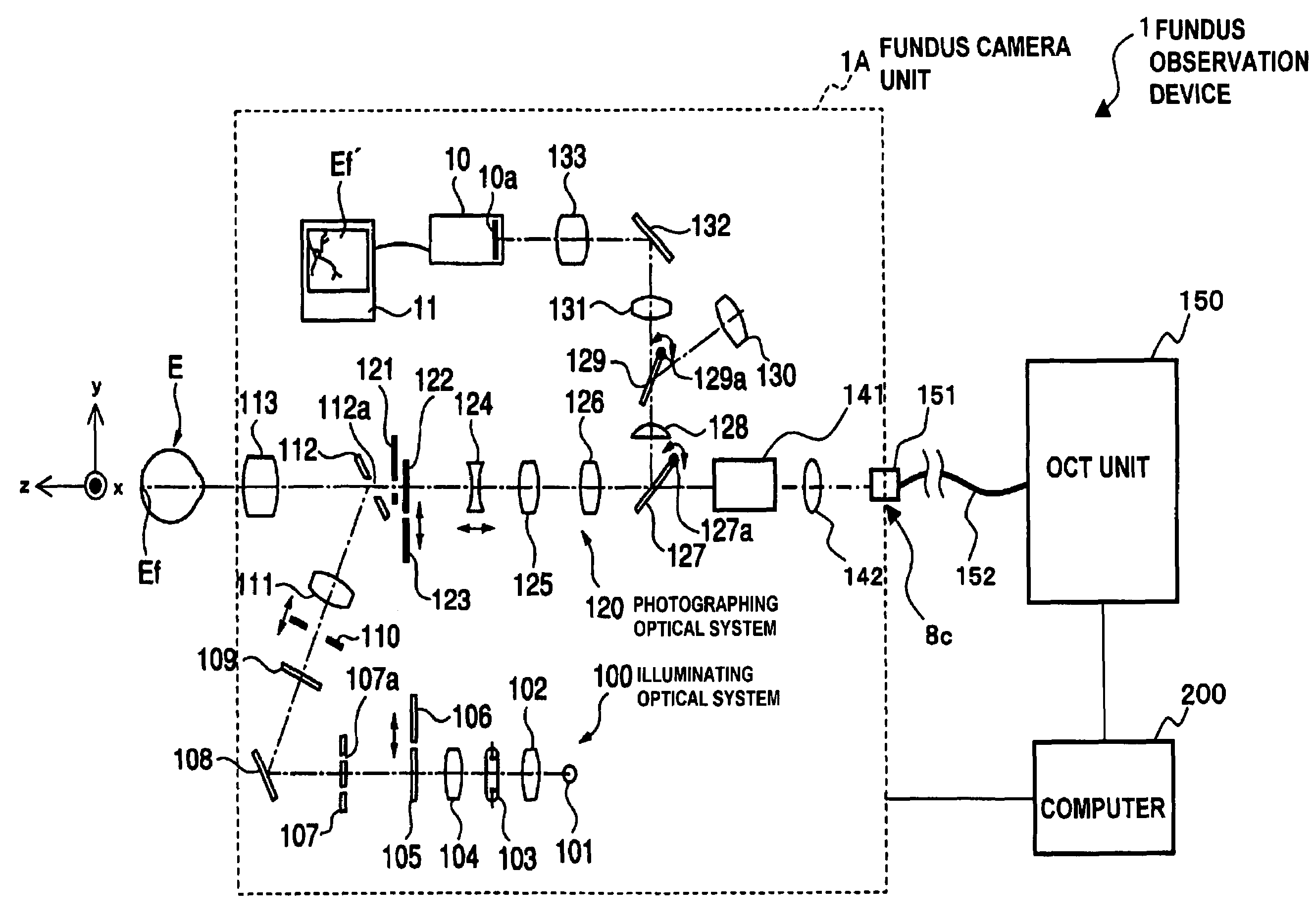
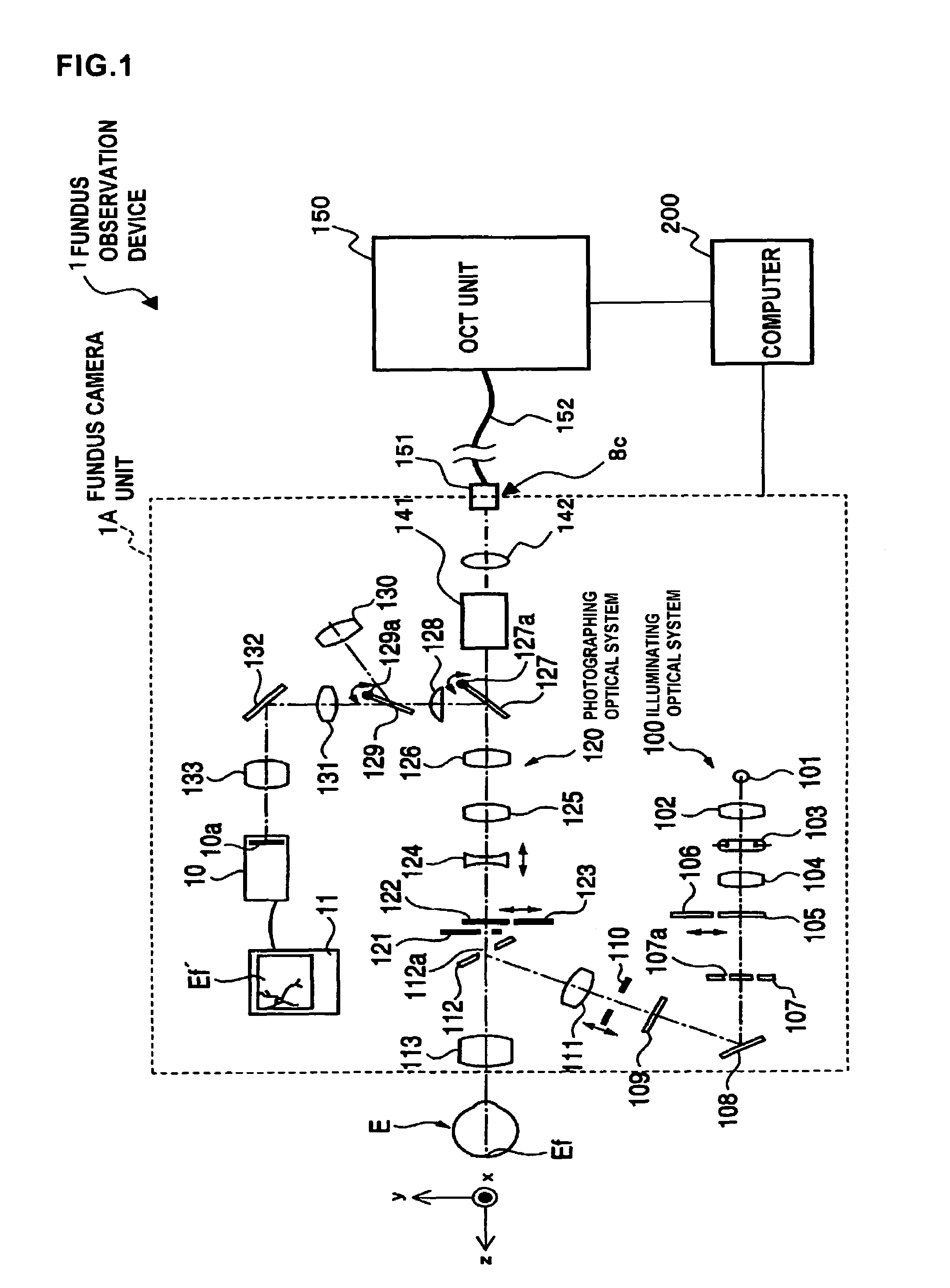
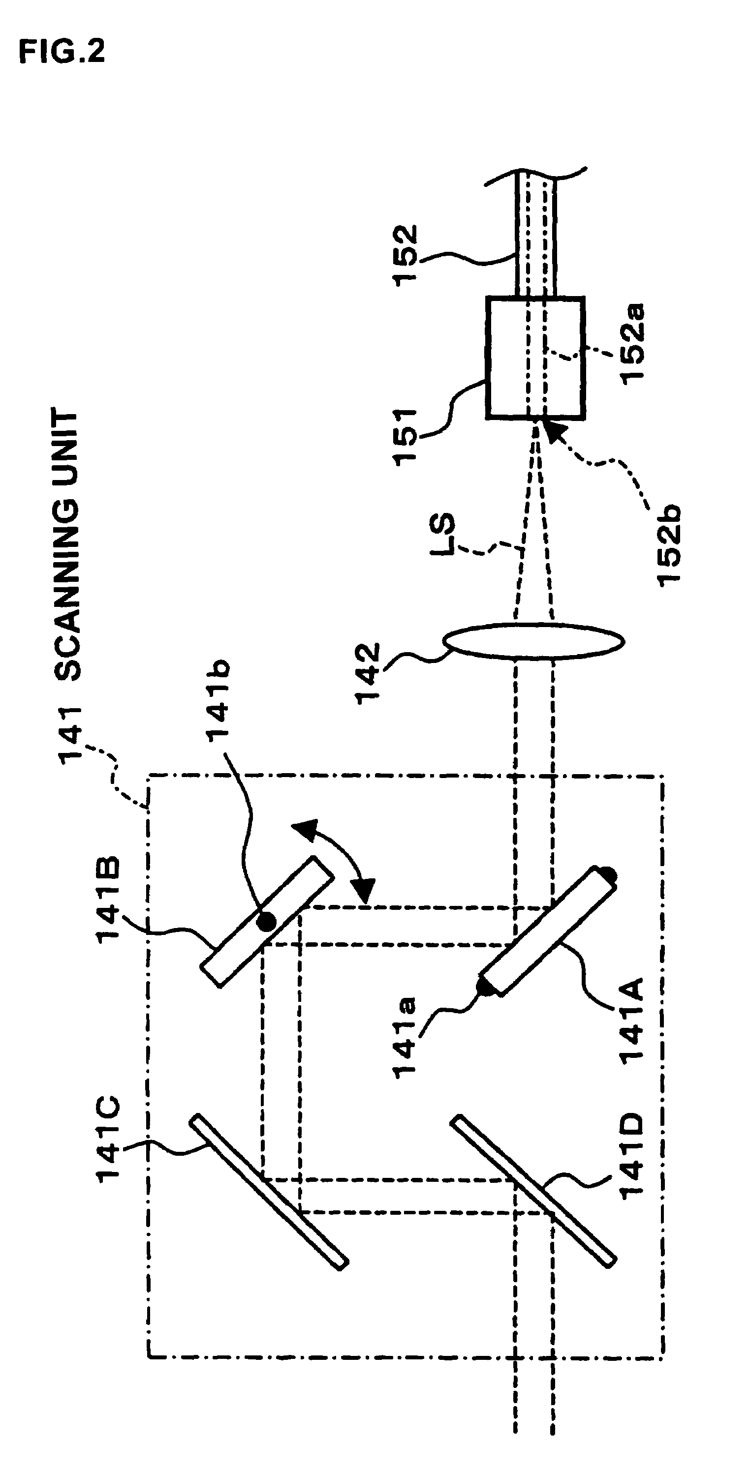
[0092]First, by referring to FIGS. 1 through 5, the composition of Embodiment 1 of the fundus observation device related to the present invention is described. FIG. 1 shows the entire constitution of the fundus observation device 1 related to the present invention. FIG. 2 shows a composition of a scanning unit 141 in a fundus camera unit 1A. FIG. 3 shows a composition of an OCT unit 150. FIG. 4 shows a hardware configuration of a computer 200. FIG. 5 shows a configuration of a control system of the fundus observation unit 1.

[The Entire Constitution]

[0093]As shown in FIG. 1, the fundus observation device 1 is comprised of a fundus camera unit 1A that functions as a fundus camera, an OCT unit 150 accommodating the optical system of an optical image measuring device (OCT device), and a computer 200 that executes various control processes, etc.

[0094]This fundus camera unit 1A constitutes the “first image forming means” and “fundus camera” of the present invention. Furthermore, the OCT u...

embodiment 2

[0207]Embodiment 2 of the fundus observation device related to the present invention is described.

[0208]In this embodiment, when an examiner designates one point on one of two images displayed in parallel, the information (designated positional information) is displayed on the other image at a position corresponding to this designated one point.

[0209]Moreover, in the present embodiment, when one point on the display image is designated, the other image including this designated one point is formed, and the information (designated positional information) is displayed at a position corresponding to the one point on the other image. In addition,

[Constitution]

[0210]One configuration example of the control system of the fundus observation device related to the present embodiment is shown in FIG. 17. This fundus observation device 1000 is provided with an optical system, hardware, and an appearance as in Embodiment 1 (ref. FIGS. 1 through 4, FIG. 42). Furthermore, the fundus observation d...

modification example

[Modification Example]

[0307]The configuration described in detail thus far in Embodiment 2 is only an example of concrete configurations for executing the fundus observation device, the fundus image display device and the fundus observation program favorably. That is, the present invention is not limited to the configuration described above; however, for example, the optional modification explained below may be implemented appropriately.

[0308]As for the Operational Features 1 through 8 of the present embodiment described previously, it is to be configured to display the coordinate value of a designated one point on the display 207 so as to make it possible to change the coordinate value that has been displayed by using the user interface 230 (operational devices such as a mouse 206). Then, it is to be configured so as to display the designated positional information at a position on the display device 207 corresponding to the changed coordinate value.

[0309]The present modification e...


PUM


Abstract

To provide a technology that makes it easy to capture a positional relation of a 2-dimensional image of the surface of a fundus oculi and a tomographic image of the fundus oculi. The fundus observation device 1 is provided with a fundus camera unit 1A for forming a 2-dimensional image of the surface of a fundus oculi Ef of an eye to be examined, an OCT unit 150 for forming a tomographic image of the fundus oculi Ef, a scanning unit 141 as well as an image processing part 220, a display 207, and a controlling part 210 of a computer 200 for displaying the 2-dimensional image formed by the fundus camera unit 1A and a tomographic image formed by the OCT unit, etc. in parallel on the display 207, and also for displaying the cross-sectional position information (attention line L, attention region P) indicating the cross-sectional position of the tomographic image on the surface of the fundus oculi Ef, so as to be overlapped with the 2-dimensional image.

Description

BACKGROUND OF THE INVENTION[0001]1. Field of the Invention[0002]The present invention relates to a fundus observation device, a fundus image display device and a fundus observation program for observing the state of the fundus oculi of an eye to be examined.[0003]2. Description of the Related Art[0004]As a fundus observation device, conventionally a fundus camera has been widely used. FIG. 42 shows one example of the appearance of a conventional fundus camera in general, and FIG. 43 shows one example of an optical system composition to be internally accommodated therein (e.g. ref. JP Patent laid-open No. 2004-350849). Furthermore, “observation” is intended to include at least a case in which photographic images are observed (observations with the naked eye may be included).[0005]First, referring to FIG. 42, an explanation is made regarding the appearance of a conventional fundus camera 1000. This fundus camera is provided with a platform 3 mounted on a base 2 slidably in the front a...

Claims


Application Information

Patent Timeline
Patent Type & Authority Patents(United States)
IPC IPC(8): A61B3/10
CPCA61B3/102
Inventor TSUKADA, HISASHIHARUMOTO, KOKIAOKI, HIROYUKIKIKAWA, TSUTOMUFUKUMA, YASUFUMI
Owner KK TOPCON
Why Eureka
Try Eureka