Temporary lighting support assembly for scaffolding systems

a technology for scaffolding and supporting parts, which is applied in outdoor lighting, lighting and heating apparatus, building scaffolds, etc. it can solve the problems of time-consuming fixture tie-up, additional safety issues, and rope and wire shaping around the job site, and achieves convenient and quick erecting. , the effect of precise work area and convenient implementation

Active Publication Date: 2009-07-28
WHELAN BRENDAN
View PDF4 Cites 35 Cited by
  • Summary
  • Abstract
  • Description
  • Claims
  • Application Information

AI Technical Summary

Benefits of technology

[0003]To overcome the above disadvantages, I have determined that a support affixed to the surrounding scaffolding members using a scaffold tube half-clamp as its attachment apparatus provides a safer and quicker way to erect temporary lighting on the job site. Since the support fixture uses a scaffold half clamp it is well known to personnel on the job site and therefore can be readily implemented. The rotational ability of the support provides flexibility to illuminate a precise work area.
[0004]This invention with its use of a scaffold clamp as a mounting apparatus allows quick installation and precise location of the light direction. The invention has the dual ability to rotate the support assembly around the scaffold member plus the ability to rotate the fixture about an axis perpendicular to the scaffold axis the upward direction. Fine-tuning of the light fixture via rotation about the bracket gives the qualified person that installs the light fixture the ability to point the light in the final direction without having to disturb the clamp assembly. The pipe attached to the scaffold clamp is of a length that enables the light fixture to setback from the work platform of the scaffold system to avoid personnel on the platform from accidental collisions.

Problems solved by technology

Temporary lighting around job sites in terms of mounting locations and ability to direct light to a precise location has used many time consuming makeshift solutions such as hanging fixtures from ropes and wires.
Tying the fixtures is time consuming and positioning requires several steps.
Rope and wire shaping around the job site create additional safety issues.
There is little flexibility to position a light fixture to illuminate a precise location as the ropes and wire has several rigidity issues.

Method used


Image

  • Temporary lighting support assembly for scaffolding systems
  • Temporary lighting support assembly for scaffolding systems
  • Temporary lighting support assembly for scaffolding systems

Examples


Embodiment Construction

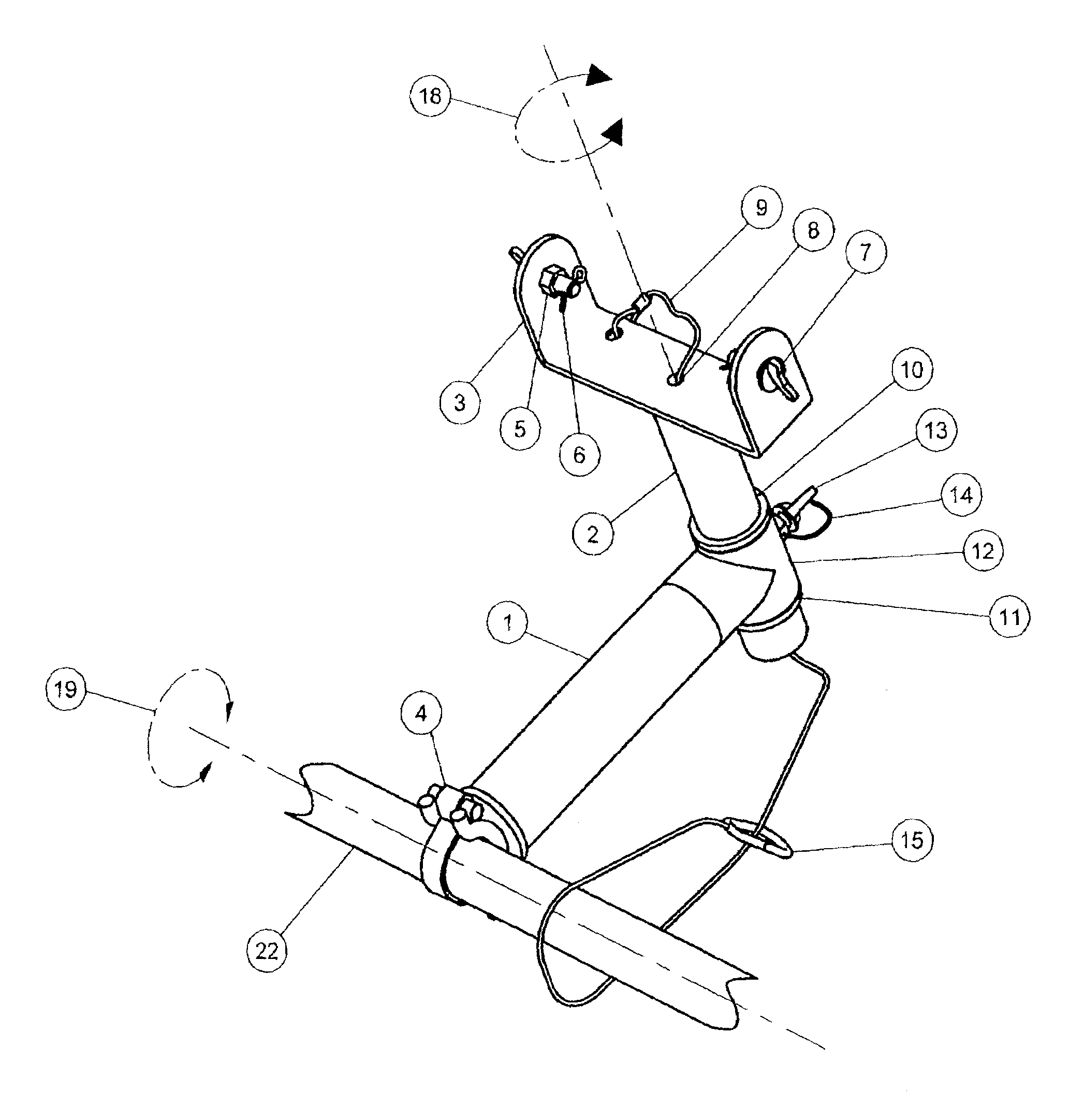
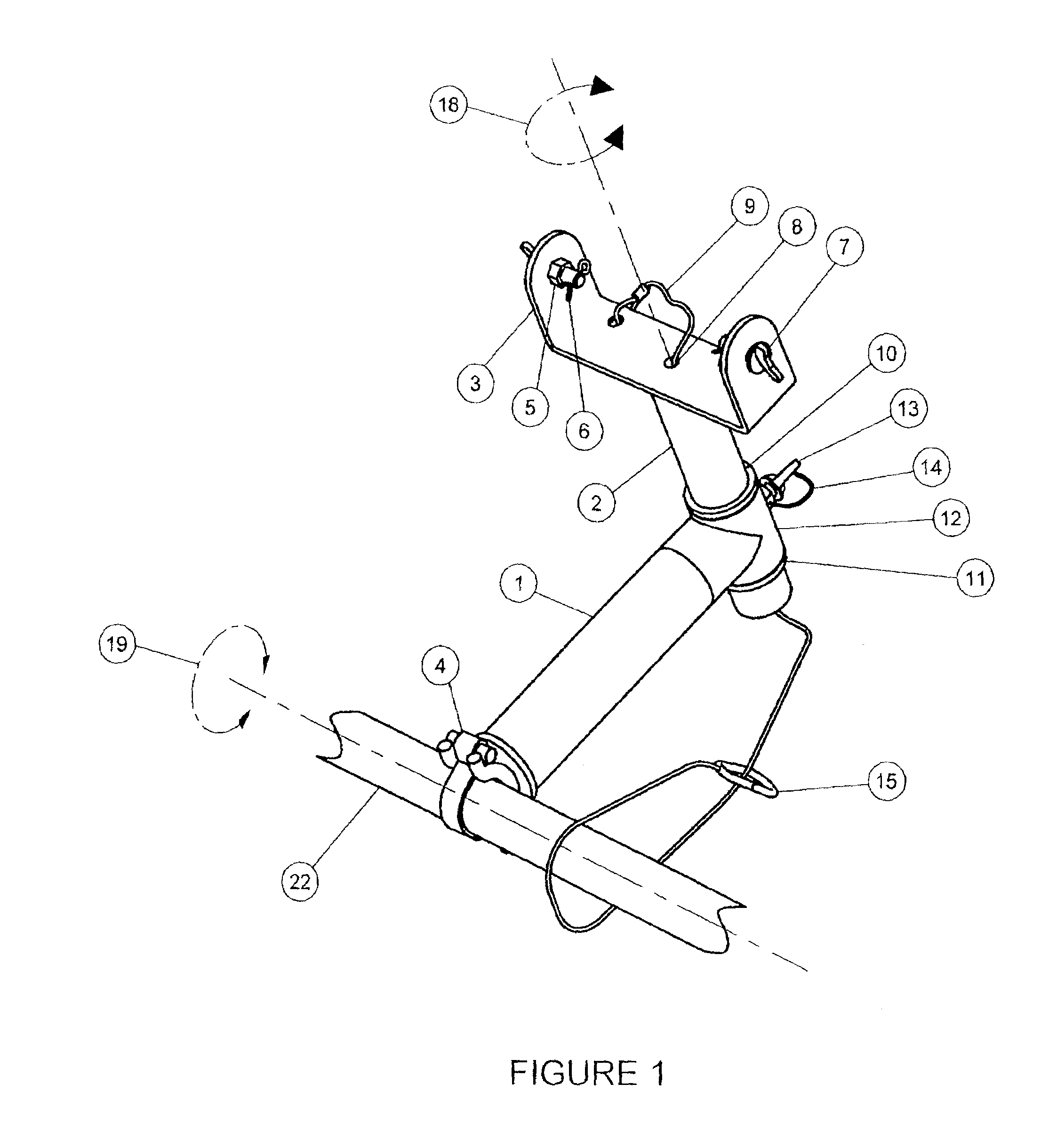
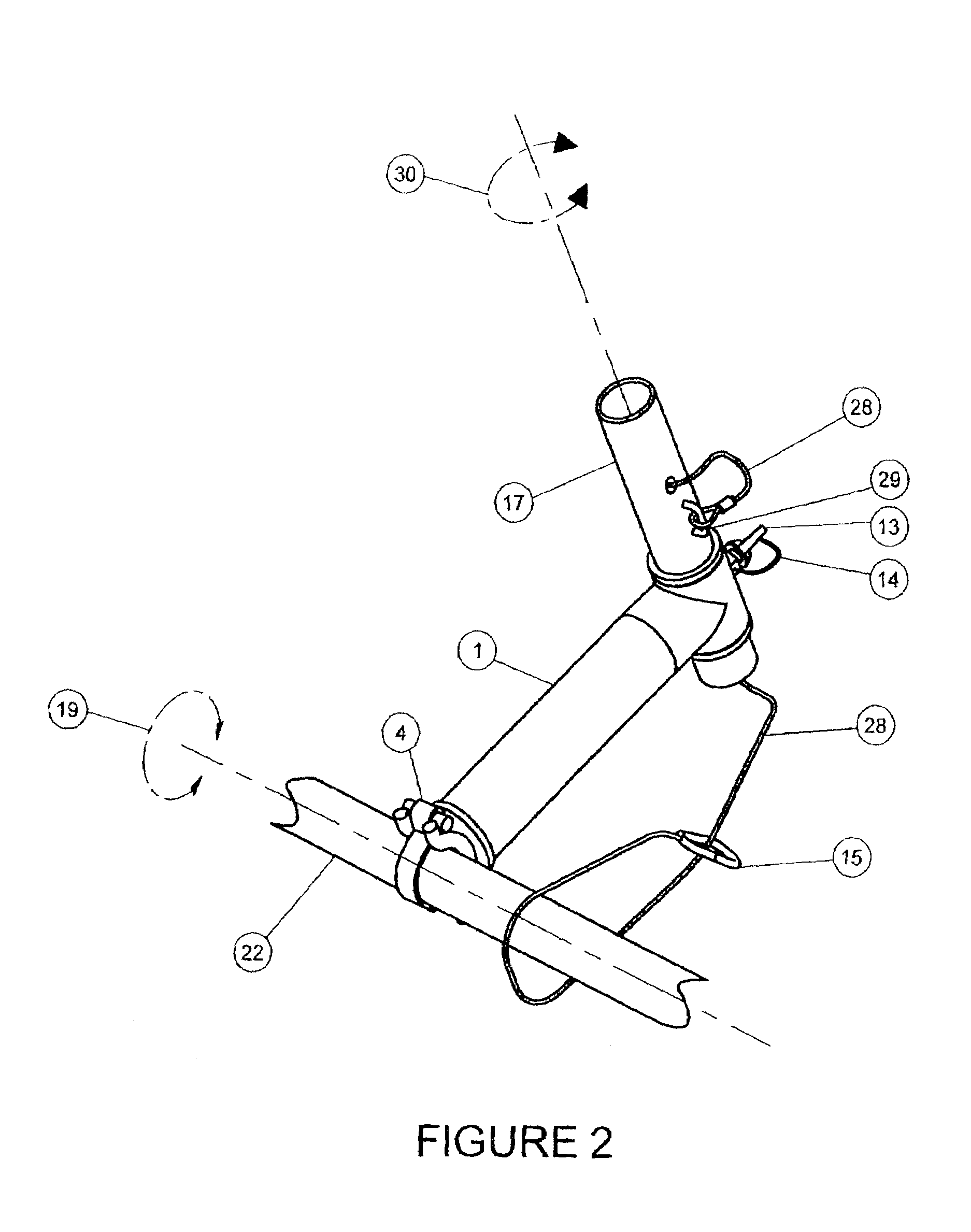
[0015]The invention illustrated comprises a support for a temporary lighting fixture that attaches itself to a horizontal scaffold pipe member 22 by means of a scaffold clamp 4. Scaffold clamp 4 is a steel clamp that can be obtained from several manufactures that is welded to pipe 1 in a precise orientation to upright the framework of the support assembly in the direction shown in FIGS. 1 and 2. FIGS. 1 and 2 show the attachment of the support assembly to a horizontal scaffold member 22. Rotation about axis 19 is unlimited until the preferred position is obtained and scaffold clamp 4 is secured. FIG. 5 shows scaffold clamp 4 in the open state during the positioning of the support assembly as mentioned above. Mounting on vertical scaffold members is accomplished in the same manner as horizontal mounting.

[0016]FIGS. 6 and 7 show that it is suitable for mounting a linear fixture 23 or mast fixture 26. A steel thin walled tee 12 that is welded to a steel pipe 1 holds steel pipe 2 captiv...


PUM


Abstract

The present invention is concerned with providing a support for temporary lighting for use with scaffolding systems. The support assembly comprises of two main components and the required fastening systems to affix lighting fixtures and mast light fixtures embodied in two configurations. The support consists of a thin walled pipe with a tube half clamp welded to one end and a thin walled tee welded to the opposite end. The clamp and tee are orientated to provide the support with a precise mounting position. A second thin walled pipe is positioned concentrically through the tee to create framework that has an angled appearance. The second pipe is maintained annular and concentric to the first pipe by means of two washer type collars welded above and below the tee that constrains both pipes to each other. A small space between the collar and tee provides the second pipe with unconstrained rotational movement. Lanyards incorporated in the support are fixed directly to the scaffold for job site safety concerns. Another aspect of the invention is the tube half clamp, which can provide quick assembly and infinite positional placement on a horizontal or vertical pipe member of a scaffolding system.

Description

FIELD OF THE INVENTION[0001]This invention provides a method of setting up temporary lighting on job sites, and more specifically, by affixing the temporary lighting to a scaffolding system by way of a support assembly.BACKGROUND OF THE INVENTION[0002]It is common on job sites to have temporary lighting for the purpose of carrying out work in dark areas and at night. Temporary lighting around job sites in terms of mounting locations and ability to direct light to a precise location has used many time consuming makeshift solutions such as hanging fixtures from ropes and wires. The typical way to affix temporary lighting is to tie the fixture to overhanging beams and scaffolding members by means of rope or wire. Often light fixtures are located on a platform or floor. This method of affixing temporary lighting requires the appropriate personnel to attach the rope or wire through the lighting fixture and pull or lower it from a suitable platform height to the location the fixture is re...

Claims


Application Information

Patent Timeline
Patent Type & Authority Patents(United States)
IPC IPC(8): F21S13/10
CPCE04G5/00F21V21/088F21W2131/1005F21W2131/10
Inventor WHELAN, BRENDANWHELAN, RICHARD
Owner WHELAN BRENDAN
Why Eureka
Try Eureka