Ultrasound diagnostic device

a diagnostic device and ultrasonic technology, applied in diagnostics, mechanical vibration separation, medical science, etc., can solve the problems of deterioration of reliability, increase in device cost and size, etc., and achieve the effect of easily generating a driving waveform with a variable duty factor

Inactive Publication Date: 2009-07-28
KONICA MINOLTA INC
View PDF11 Cites 18 Cited by
  • Summary
  • Abstract
  • Description
  • Claims
  • Application Information

AI Technical Summary

Benefits of technology

[0007]In view of the above-stated problems, it is an object of the present invention to provide a small ultrasound diagnostic device at a low cost that enables the appropriate control with a single power supply unit so as to give a predetermined transmission power to a driving waveform different for each mode without excess or deficiency and without affecting properties of the driving waveform.
[0010]With the above-stated configurations, an acoustic power of the ultrasound transmitted from the ultrasound generation unit can be controlled without making the transmission amplitude variable, and an unnecessary increase of harmonics due to the change of duty factor can be suppressed. Therefore, an increase of the acoustic power and an increase of a surface temperature, which result from the transmission of unnecessary energy, can be suppressed as well.
[0012]With this configuration, an acoustic power of the ultrasound transmitted from the ultrasound generation unit can be controlled without making a transmission amplitude variable for each mode, thus suppressing an increase in unnecessary second harmonics resulting from a change of duty factor. Thereby, as well as the suppression of an increase in acoustic power and an increase in surface temperature resulting from the transmission of unnecessary energy, the driving amplitude of driving waveforms for the respective modes can be made uniform, whereby it is unnecessary to incorporate a plurality of and quick-response power supply units.
[0014]With this configuration, the multiplication unit multiplies a single pulse or a burst pulse generated by the fundamental waveform generation unit and a continuous rectangular wave with a variable duty factor that is generated by the modulated wave generation unit. Thus, a driving waveform with a variable duty factor can be generated easily by simply adding a modulated wave generation unit and a multiplication unit to an existing fundamental waveform generation unit without the use of a complicated logic circuit.

Problems solved by technology

In the above-stated conventional ultrasound diagnostic device, however, since a plurality of power supplies and a high-speed power supply should be used, the power supply unit is increased in size, which causes the problems of an increase in cost and size of the device and moreover deterioration of the reliability.

Method used


Image

  • Ultrasound diagnostic device
  • Ultrasound diagnostic device
  • Ultrasound diagnostic device

Examples


embodiment 1

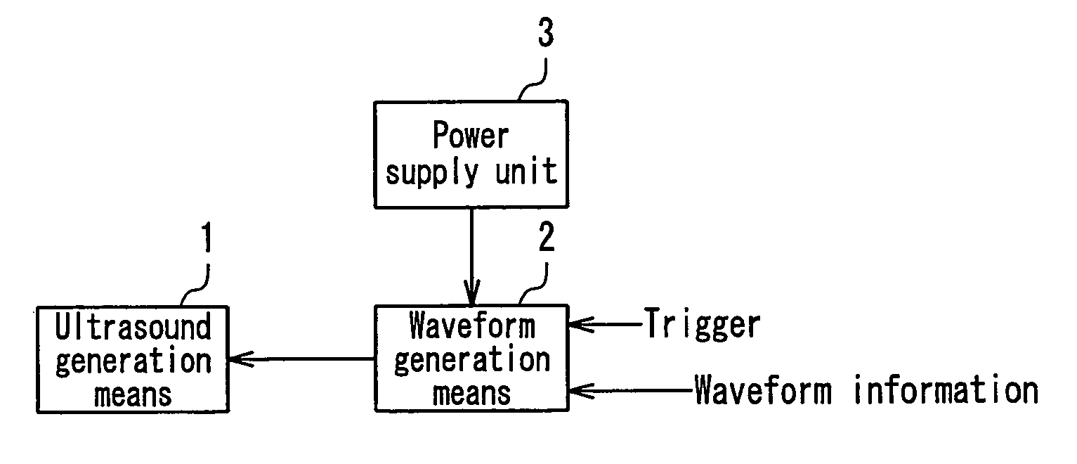
[0023]FIG. 1 is a block diagram showing one exemplary configuration of an ultrasound diagnostic device according to Embodiment 1 of the present invention.

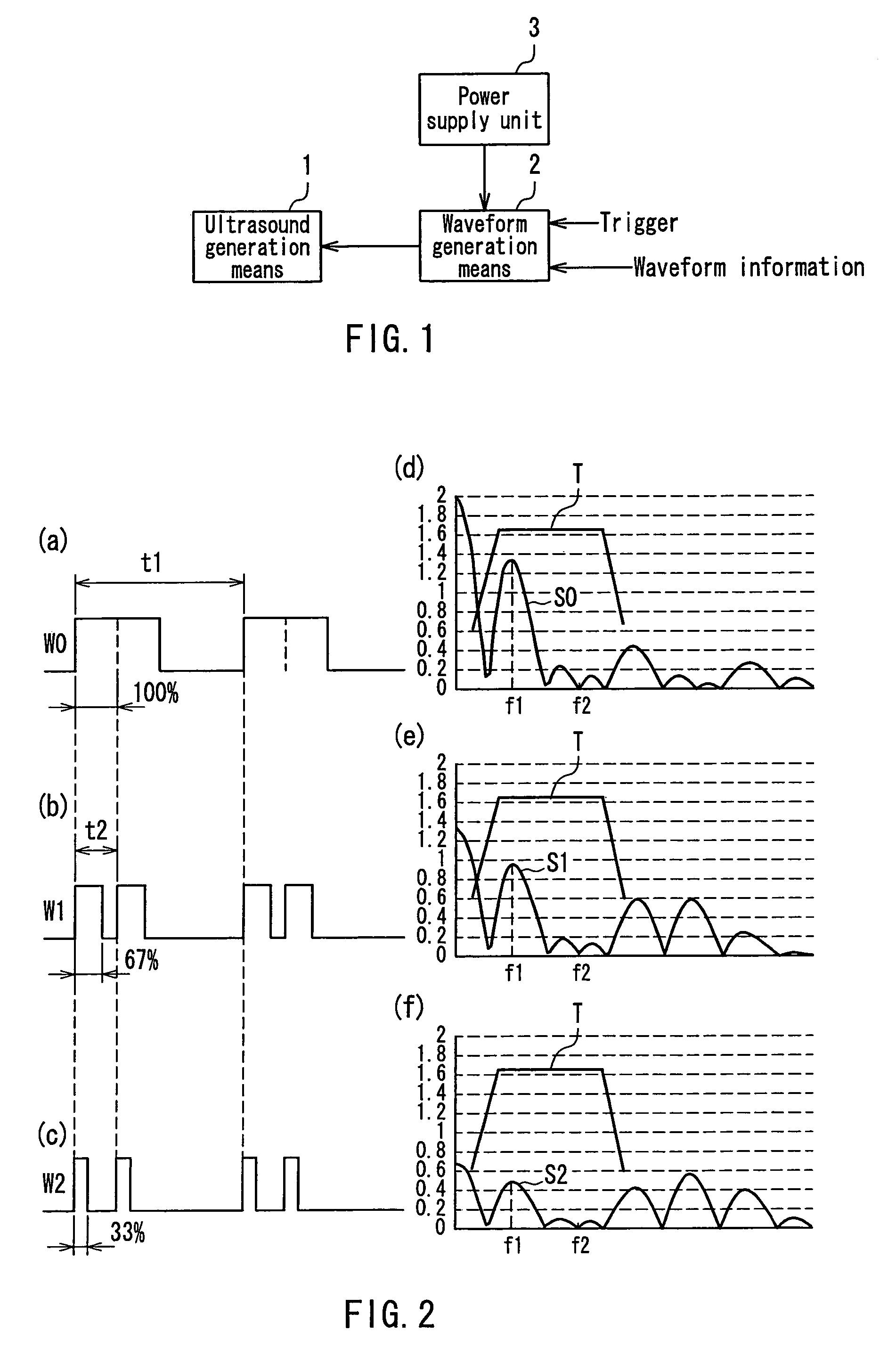
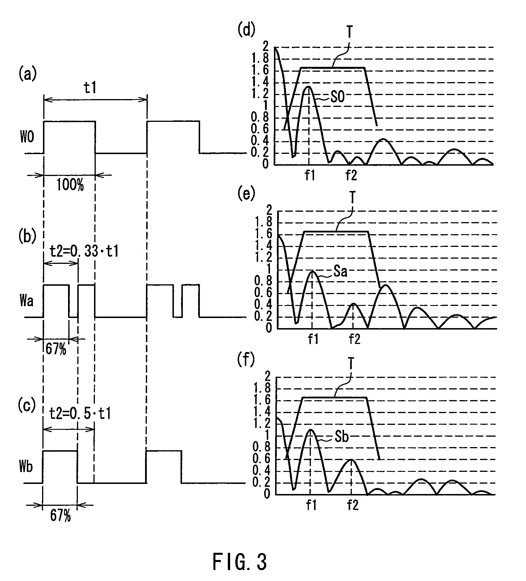
[0024]In FIG. 1, the ultrasound diagnostic device of the present embodiment is composed of: an ultrasound generation means 1; a waveform generation means 2 and a single power supply unit 3. The ultrasound generation means 1 transmits ultrasound. The waveform generation means 2 generates a single pulse or a burst pulse so as to drive the ultrasound generation means 1, in which a duty factor of a single pulse or a burst pulse is variable in the time units of a period corresponding to a frequency outside the frequency band of the frequency characteristics (T) of the ultrasound generation means 1 in FIG. 2 (higher-frequency side than (T)). The power supply unit 3 determines the amplitude of a driving waveform that is generated by the waveform generation means 2.

[0025]The waveform generation means 2 drives the ultrasound generation mean...

embodiment 2

[0035]FIG. 4 is a block diagram showing one exemplary configuration of an ultrasound diagnostic device according to Embodiment 2 of the present invention.

[0036]In FIG. 4, a duty factor of a driving waveform from a waveform generation means 2 is made variable so as to control an acoustic power, which is similar to Embodiment 1. In the present embodiment, in accordance with current mode information that is generated by a mode control unit 5, a waveform control unit 4 further determines a driving waveform, which is to be generated by the waveform generation means 2, so as to correspond to waveform information that is determined for each mode corresponding to the mode information at present.

[0037]Due to a given upper limit of the acoustic power, in the B-mode and the M-mode, which emphasize resolution in general, a peak of the amplitude should be increased with a reduced wave number. In the Doppler (including two-dimensional Doppler) mode, sensitivity is emphasized, and therefore the wa...

embodiment 3

[0040]FIG. 5 is a block diagram mainly showing an exemplary internal configuration of a waveform generation means 2 in an ultrasound diagnostic device according to Embodiment 3 of the present invention. The waveform generation means 2 shown in FIG. 5 may be applied to Embodiment 1 and Embodiment 2. FIG. 6 is a waveform chart of signals at the respective portions in FIG. 5.

[0041]In FIG. 5, the waveform generation means 2 is composed of a fundamental wave generation means 6, a modulated wave generation means 7, a multiplication means 8 and a driving means 9.

[0042]The following describes the operation of the thus configured waveform generation means 2, with reference to FIG. 5 and FIG. 6.

[0043]The fundamental waveform generation means 6 and the modulated wave generation means 7 are triggered by a trigger waveform A, and the waveforms output from both means are in synchronization with each other. The fundamental waveform generation means 6 generates a driving waveform B that is for driv...


PUM


Abstract

A small ultrasound diagnostic device is provided at a low cost that enables the appropriate control by a single power supply unit so as to give a predetermined transmission power to a driving waveform different for each mode without excess or deficiency and without affecting properties of the driving waveform. The ultrasound diagnostic device includes: an ultrasound generation unit (1) that transmits ultrasound; a waveform generation unit (2) that generates a single pulse or a burst pulse whose duty factor is variable in units of a time that is a period corresponding to a frequency outside a frequency band of the ultrasound generation unit (1) so as to drive the ultrasound generation unit (1); and a single power supply unit (3) that determines an amplitude of a driving waveform generated by the waveform generation unit (2). Thereby, an acoustic power of the transmitted ultrasound can be controlled without making the transmission amplitude variable.

Description

TECHNICAL FIELD[0001]The present invention relates to an ultrasound diagnostic device used in the medical field.BACKGROUND ART[0002]As conventional ultrasound diagnostic devices, those described in JP2001-087263A and JPH08(1996)-280674A are known.[0003]In general, ultrasound diagnostic devices employ modes called the B-mode, the M-mode, the Doppler mode (hereinafter referred to as D-mode) and the color or two-dimensional Doppler mode (hereinafter referred to as C-mode) alone or in combination. At this time, a transmission power is controlled so that a surface temperature of a portion of an ultrasound generation means contacting with a living body and an acoustic power from the ultrasound generation means to a living body do not exceed predetermined levels. Further, the transmission is conducted with a frequency, an amplitude and a wave number of a driving waveform that are determined for each mode. Thus, for a driving waveform that is different for each mode, a transmission power is...

Claims


Application Information

Patent Timeline
Patent Type & Authority Patents(United States)
IPC IPC(8): A61B8/00B06B1/02
CPCA61B8/00B06B1/0215A61B2560/0214
Inventor NAKAMURA, YASUHIROUCHIKAWA, AKIKOAKIYAMA, HISASHINISHIGAKI, MORIOYOSHITOMI, HIDENORI
Owner KONICA MINOLTA INC
Why Eureka
Try Eureka