Systems, methods, and apparatus for a kinetic energy absorbing device

a technology of energy absorption device and energy absorbing material, which is applied in the direction of radio frequency controlled devices, instruments, packaged goods, etc., can solve the problems of increasing the risk of significant impact or bumping on the electronic device, and affecting the device's operation

Inactive Publication Date: 2009-07-28
GENERAL ELECTRIC CO
View PDF7 Cites 11 Cited by
  • Summary
  • Abstract
  • Description
  • Claims
  • Application Information

AI Technical Summary

Benefits of technology

[0007]In one aspect, an apparatus for absorbing an impact imparted to a device includes device, and an impact absorbing material affixed to the exterior of the device in which the impact absorbing material is permanently deformed upon encountering an impact event of sufficient force. The material will plastically deform as the material absorbs the energy of impact. By deforming plastically, the material provides a significantly higher level of shock absorption, while at the same time providing a visual record of the transportable device having been dropped. The improved shock absorption improves the reliability and longevity of the transportable device. Examples of the device include transportable devices.
[0010]In a further aspect, the impact absorbing material is made from a crumple zone material that is tuned to absorb a predetermined number of impact events whereupon the crumple zone material becomes permanently deformed beyond a certain visual threshold. The permanently deformed impact absorbing material provides a visual indication of mechanical shock, which is helpful to the manufacturer or the maintenance and service provider of the transportable device in determining that the transportable device has been physically abused to the extent that the financial burden of replacing the transportable device is beyond the responsibility to the manufacturer, or the maintenance or service provider. This further aspect provides both mechanical protection to the transportable device along with a visual indication of mechanical abuse.

Problems solved by technology

Thus, the electronic devices are at a much greater risk for a significant amount of impact or bumping, and from which the devices need to be protected or hardened against.
Though a straightforward and simple solution, this approach suffers from four main limitations when applied to certain types of applications.
First, the approach of adding a significant amount of absorbing material tends to bulk up the device and defeats the very desire to make them lighter and more portable.
Second, these forms of absorbing material can sometimes be inappropriate for certain working environments, such as in the medical field.
Third, the use of sleeves or covers can be cumbersome to install and remove, and may also impede the operation of the device.
Finally, conventional systems often give no indication of the extent of, if any at all, the severity of the impact event and provide no lasting feedback to the users that they might be frequently inappropriately mishandling the devices.

Method used


Image

  • Systems, methods, and apparatus for a kinetic energy absorbing device
  • Systems, methods, and apparatus for a kinetic energy absorbing device
  • Systems, methods, and apparatus for a kinetic energy absorbing device

Examples


an embodiment

Apparatus of an Embodiment

[0054]In the previous section, a system level overview of the operation of an embodiment was described. In this section, the particular apparatus of such an embodiment are described by reference to a series of diagrams.

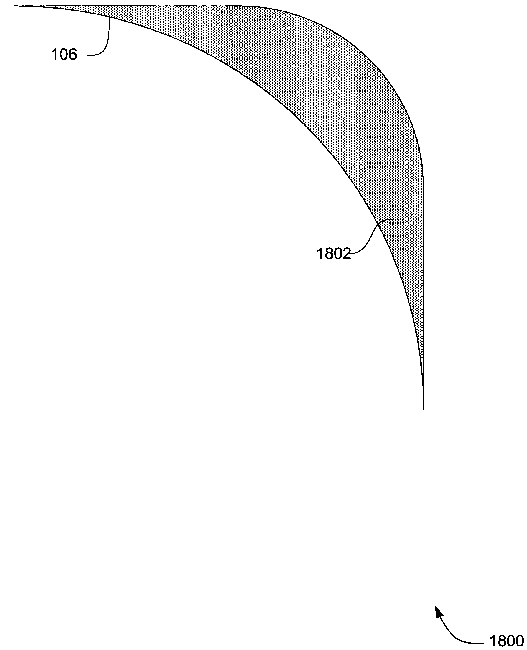
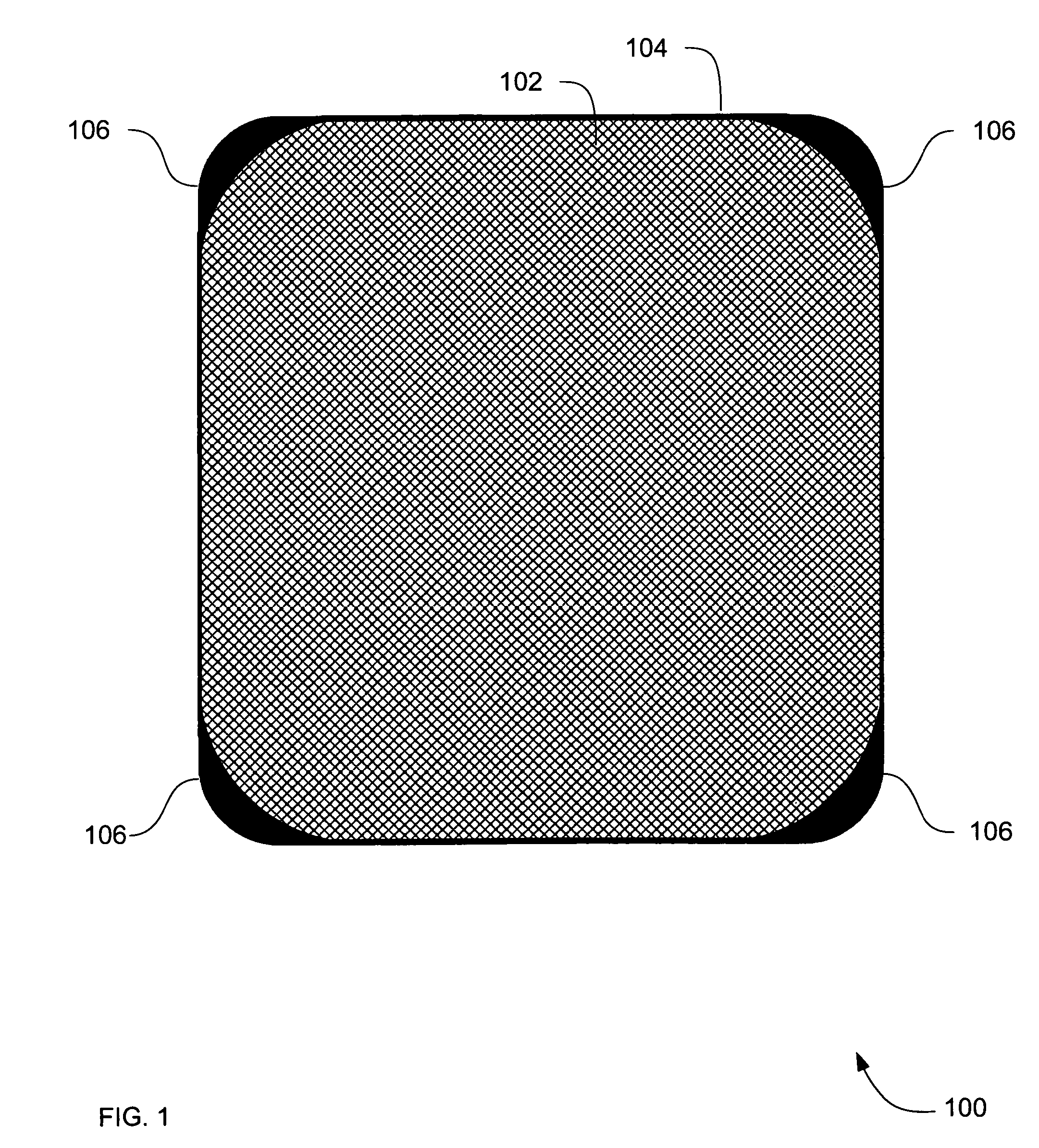
[0055]FIG. 5 is a cross section diagram of impact absorbing material 500, according to an embodiment. Impact absorbing material 500 is one embodiment of impact absorbing material 106 in FIG. 1.

[0056]The impact absorbing material 500 includes a contoured surface 502 that is adapted to a surface (not shown) of a transportable device so that the entire length of the contoured surface 502 integrates with the surface of the transportable device.

[0057]The impact absorbing material 500 also has a convex surface 504 that contacts other objects during an impact. The shape of absorbing material 500 defined by the contoured surface 502 and convex surface 504 are particularly well adapted for attachment to a conventional solid-sate X-Ray detector. Other ...


PUM


Abstract

Systems, methods and apparatus are provided through which an impact absorbing material is affixed to a transportable device to protect the transportable device from impact with another object. In some embodiments, the impact absorbing material is a crumple zone material that has plastic deformation characteristics.

Description

FIELD OF THE INVENTION[0001]This invention relates generally to an energy absorbing material, and more particularly to an energy absorbing material attached to a device.BACKGROUND OF THE INVENTION[0002]In a world of ever-increasing miniaturization of electronic devices, more and more equipment and / or devices are being designed in portable or hand-held packaging. These devices are transportable and are either free standing and hand-held in conventional use, or are removable from the structure within which the hand-held device is often mounted. Transportable devices include cellular phones, personal digital assistants (PDAs), and laptops. More recently, with an increase in demand for flexibility in imaging needs for medical and industrial use, fixed X-Ray detectors are being redesigned and being called upon for transportable uses.[0003]Interest in transportable uses of electronic devices, and the decrease in the size and weight of the devices is causing testing equipment as well hand-...

Claims


Application Information

Patent Timeline
Patent Type & Authority Patents(United States)
IPC IPC(8): H01L27/146B65D81/02
CPCH01L27/14658
Inventor BHATT, VIVEK
Owner GENERAL ELECTRIC CO
Why Eureka
Try Eureka