

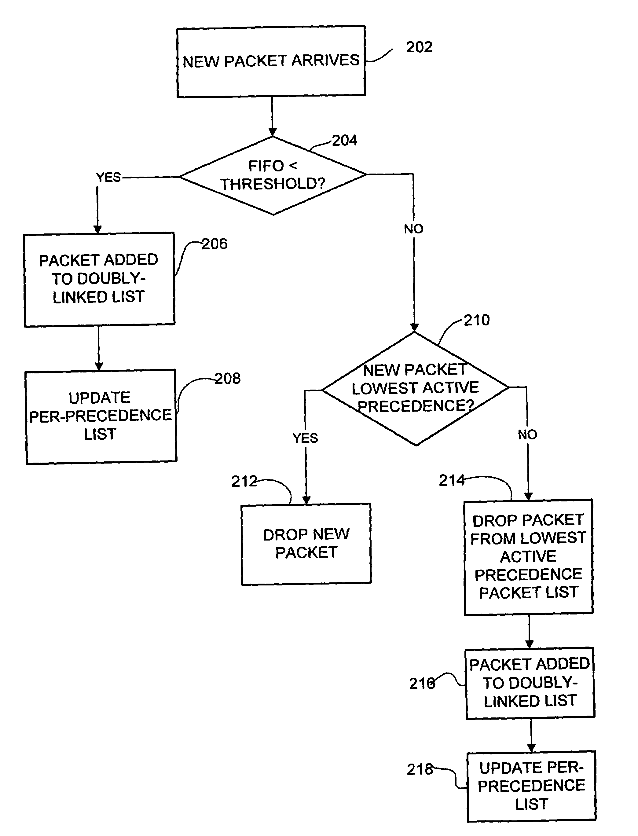
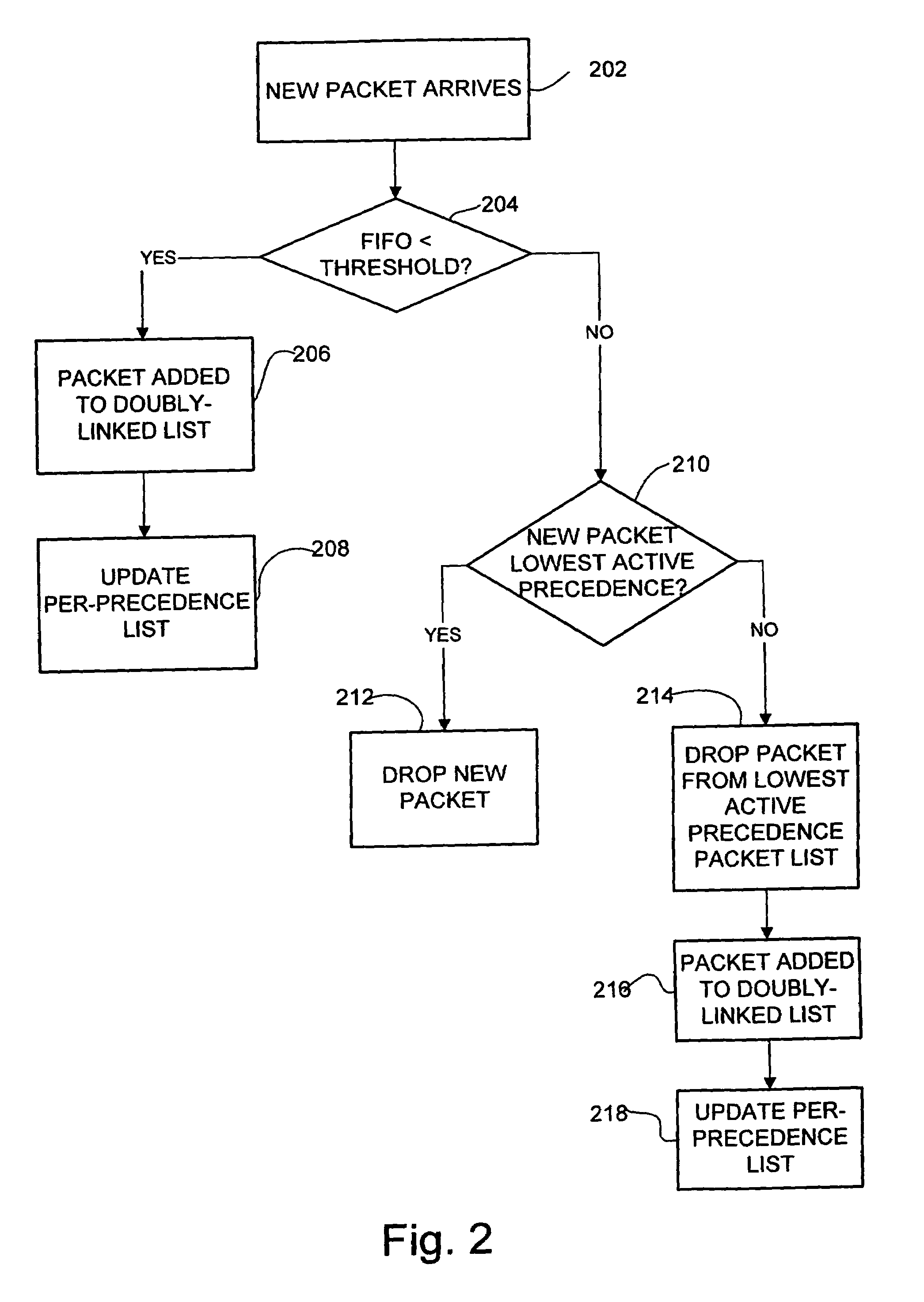
Method and system for providing delay bound and prioritized packet dropping
a delay bound and priority technology, applied in the field of data networking, can solve the problems of difficult to achieve clear guidance, reduce the quality of calls of lower level precedence, and difficulty in tuning thresholds
- Summary
- Abstract
- Description
- Claims
- Application Information
AI Technical Summary
Benefits of technology
Problems solved by technology
Method used
Image

Examples
Embodiment Construction
[0018]The following description is presented to enable one of ordinary skill in the art to make and use the invention. Descriptions of specific embodiments and applications are provided only as examples and various modifications will be readily apparent to those skilled in the art. The general principles described herein may be applied to other embodiments and applications without departing from the scope of the invention. Thus, the present invention is not to be limited to the embodiments shown, but is to be accorded the widest scope consistent with the principles and features described herein. For purpose of clarity, details relating to technical material that is known in the technical fields related to the invention have not been described in detail.
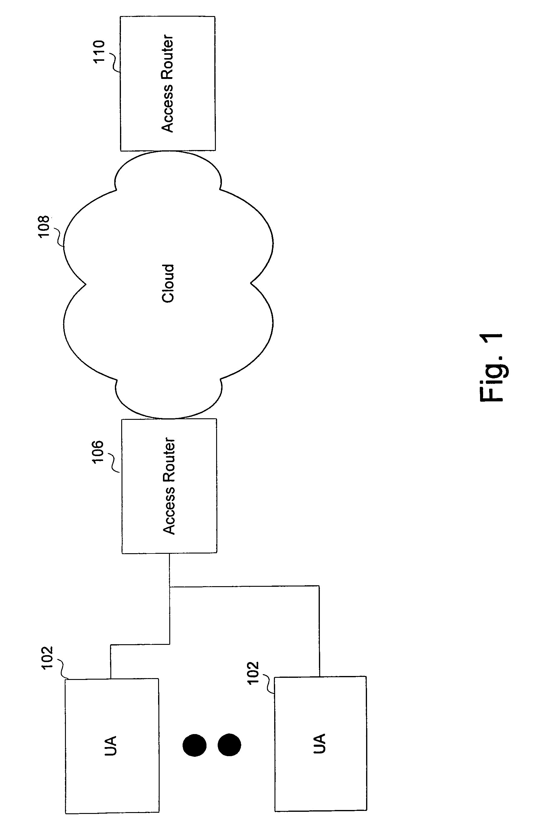
[0019]The present invention is described herein with reference to a representative application but is not limited to this application. In the representative application, calls such as voice or video calls are carried across a packet n...
PUM
 Abstract
Description
Claims
Application Information