
Method of forming a tubular axle

a tubular axle and flange technology, applied in the field of forming tubular axles, can solve the problems of complex variation of the thickness of the flange relative to the interflange section along a single member, not ideal for torsional and other loads, and achieve the effect of maximum manufacturing versatility, desirable bending and torsional loading characteristics, and increased strength

Active Publication Date: 2009-08-04
MERITOR LIGHT VEHICLE TECH LLC
View PDF10 Cites 7 Cited by
  • Summary
  • Abstract
  • Description
  • Claims
  • Application Information

AI Technical Summary

Benefits of technology

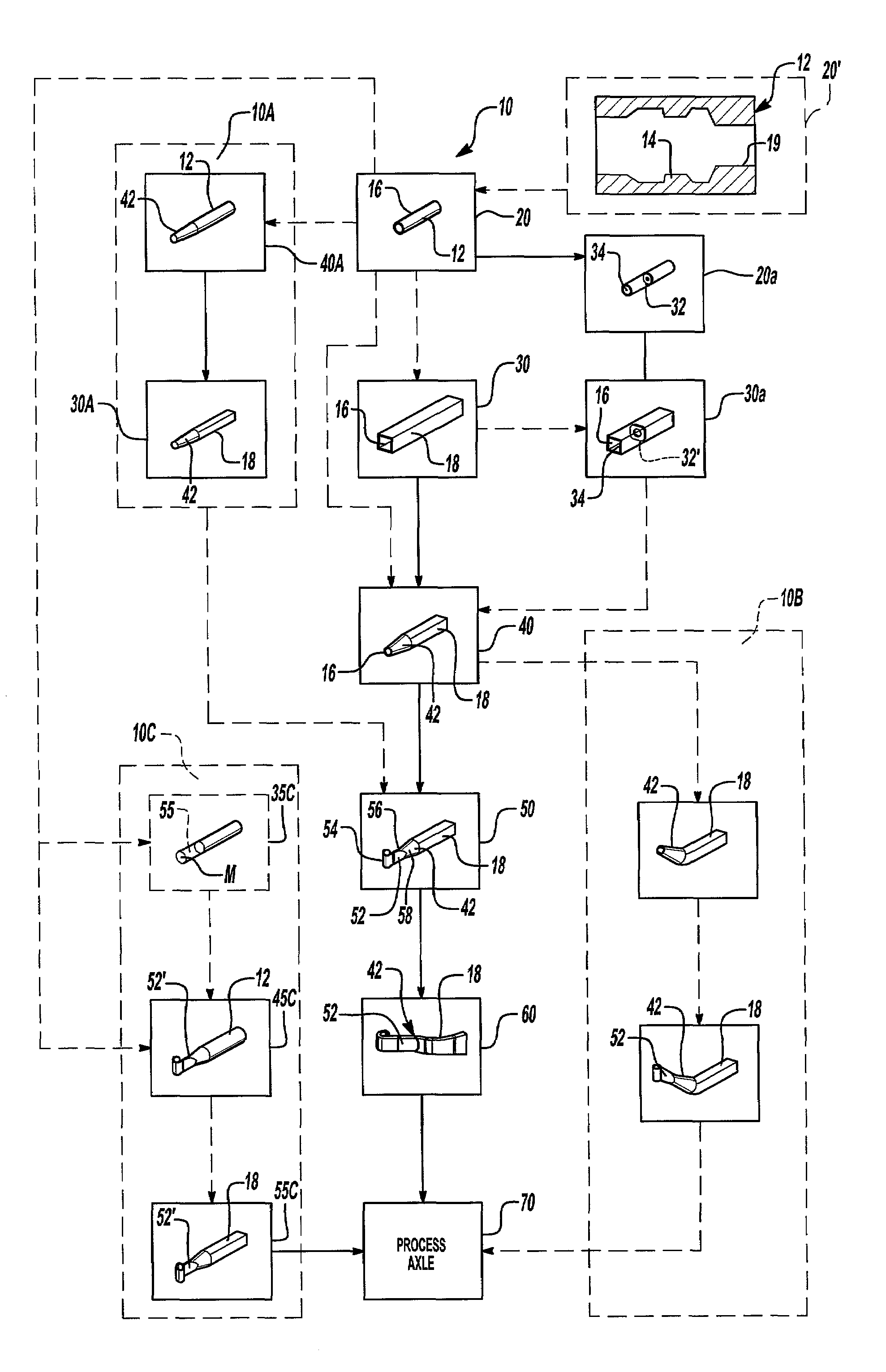
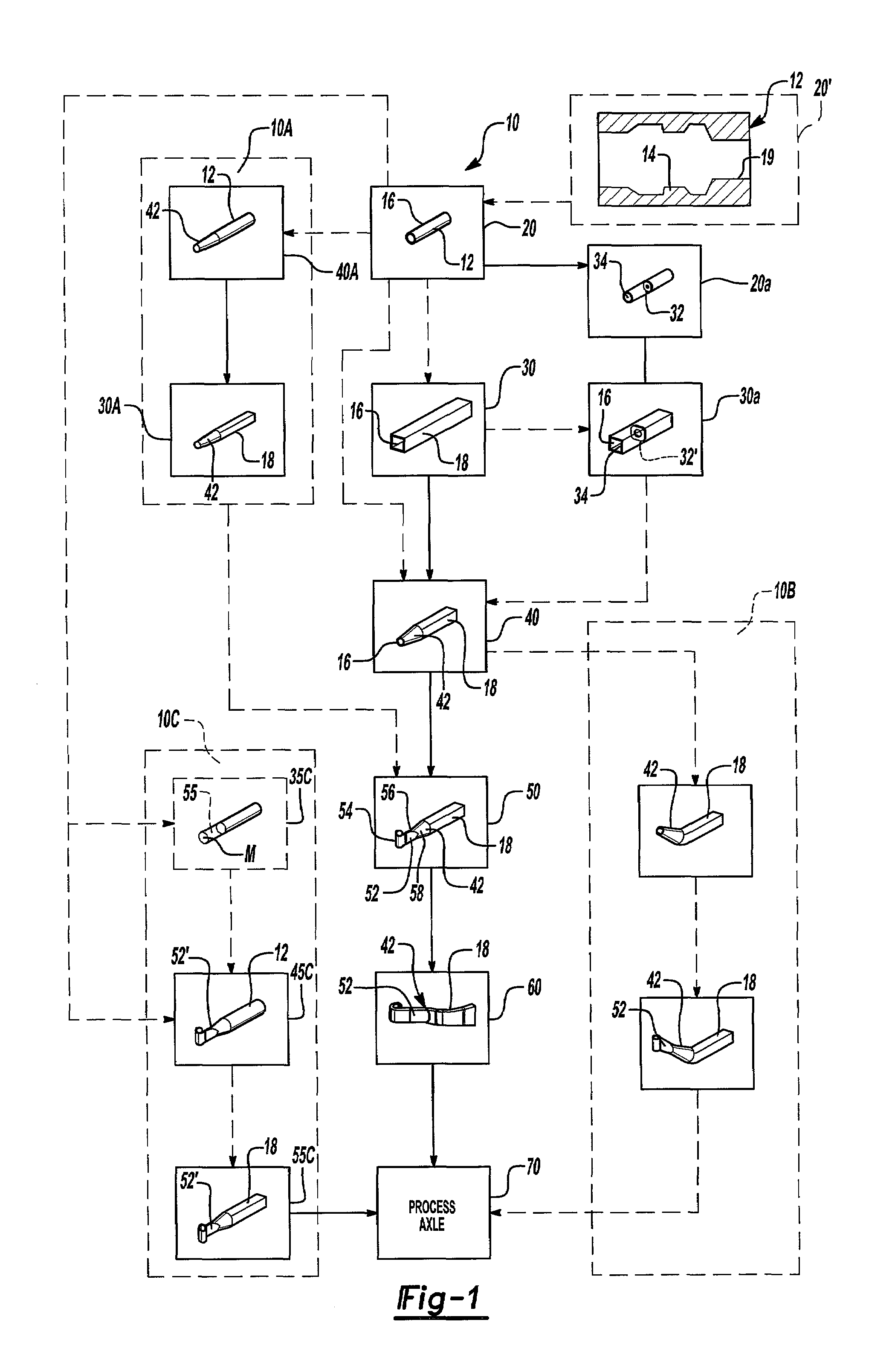
[0005]The forming method according to the present invention provides a versatile method of forming a hollow axle assembly. A hollow member such as a cylindrical tube is formed into a polygonal cross-section having an end portion. Bulkheads may be located into the hollow member prior or after this polygonal forming step to improve proximate strength and transfer suspension bending moments. The end portions are formed to provide round or frustroconical portions to receive a preformed king pin boss. The members are welded together and the king pin boss and tubular member are bent to a desired axle shape. The axle may then be processed by heat treating, quenching, and tempering. Straightening of the axle may also be desirable.
[0009]The present invention therefore provides multiple method sequences resulting in maximum manufacturing versatility. The axle assembly formed according to the present invention provide an integral hollow section which lightens the axle and provides desirable bending and torsional loading characteristics. Axle assemblies manufactured according to the present invention have demonstrated increased strength while reducing weight from approximately 185 pounds to 110 pounds.

Problems solved by technology

Front axles are typically constructed from a forged I-beam, which is suitable for bending loads but typically not ideal for torsional and other loads.
Tailoring of the I-beam to a desired application is typically limited to varying the overall beam size and flange thickness.
Variation of the flanged thickness relative to the inter-flange section along a single member is complicated and may provide only limited weight and strength versatility.
Disadvantageously, this sectional component approach is expensive, may be difficult to control and typically results in a relatively heavy axle assembly.

Method used


Image

  • Method of forming a tubular axle
  • Method of forming a tubular axle

Examples


Embodiment Construction

[0011]FIG. 1 illustrates a flow chart of the present invention axle forming process 10. The process 10 is initiated with a hollow member 12. Preferably, the hollow member 12 is preferably a cylindrical tubular member 12 as indicated at step 20, but may also be a polygonal member as indicated in step 30. It is to be understood that swaging is a preferred method of forming, however other methods may be used to form the hollow member 12. Although clearly not limited to only such sizes, a ⅜th inch wall thickness tube is provided to carry approximately 12,000 pounds; 9 / 16th inch wall thickness tube is provided to carry approximately 14,600 pounds; and ¾th inch wall thickness tube is provided to carry approximately 18,000 pounds after the process sequence of the present invention.

[0012]Furthermore, the tubular member 12 may alternatively include preformed multi-wall thickness lengths 14 as indicated at step 20′. By providing multi-wall thickness lengths 14, the tubular member 12 includes ...


PUM

PropertyMeasurementUnit
Thicknessaaaaaaaaaa
Sizeaaaaaaaaaa
Shapeaaaaaaaaaa

Abstract

A method of forming an axle assembly having a hollow member. A hollow member such as a cylindrical tube is formed into a polygonal cross-section having an end portion. Bulkheads maybe located into the hollow member prior or after the polygonal forming step to improve proximate strength and transfer suspension bending moments. The end portions are formed to receive a preformed king pin boss having an end portion of approximately the same size as the frustoconical end. The members are welding together and the king pin and hollow member are bent to a desired axle shape. In another method sequence, the kingpin boss is directly formed into the end of the hollow member.

Description

[0001]The present application is a continuation-in-part of U.S. application Ser. No. 09 / 935,026, filed Aug. 22, 2001 now abandoned.BACKGROUND OF THE INVENTION[0002]The present invention relates to an axle having a hollow section, and more particularly to a method of forming a complete axle from a singular tubular member.[0003]Front axles are typically constructed from a forged I-beam, which is suitable for bending loads but typically not ideal for torsional and other loads. Tailoring of the I-beam to a desired application is typically limited to varying the overall beam size and flange thickness. Variation of the flanged thickness relative to the inter-flange section along a single member is complicated and may provide only limited weight and strength versatility. Hollow tubular members have also been used to lighten axle assemblies and improve torsional loading characteristics. Typically, rectangular or cylindrical tube sections are welded to other preformed axle portions such as g...

Claims


Application Information

Patent Timeline
IPC IPC(8): B21D53/90B21D53/88B23P15/00B60G7/00B62D7/18
CPCB23P15/00B60G2206/312B60G2206/32B60G2206/81Y10T29/49622B60G2206/82013B60G2206/8402Y10T29/49826B60G2206/8201
Inventor PLATNER, DAVID K.
Owner MERITOR LIGHT VEHICLE TECH LLC
Learn More