Device and method for pulling bullets from cartridges

a cartridge and cartridge technology, applied in the direction of weapons, ammunition, weapon components, etc., can solve the problems of relatively complex and expensive manufacturing of cartridge devices, similarly damaging bullets, etc., and achieve the effects of reducing diameter, increasing c ring diameter, and increasing internal diameter

Inactive Publication Date: 2009-08-04
LEE RICHARD J
View PDF15 Cites 87 Cited by
  • Summary
  • Abstract
  • Description
  • Claims
  • Application Information

AI Technical Summary

Benefits of technology

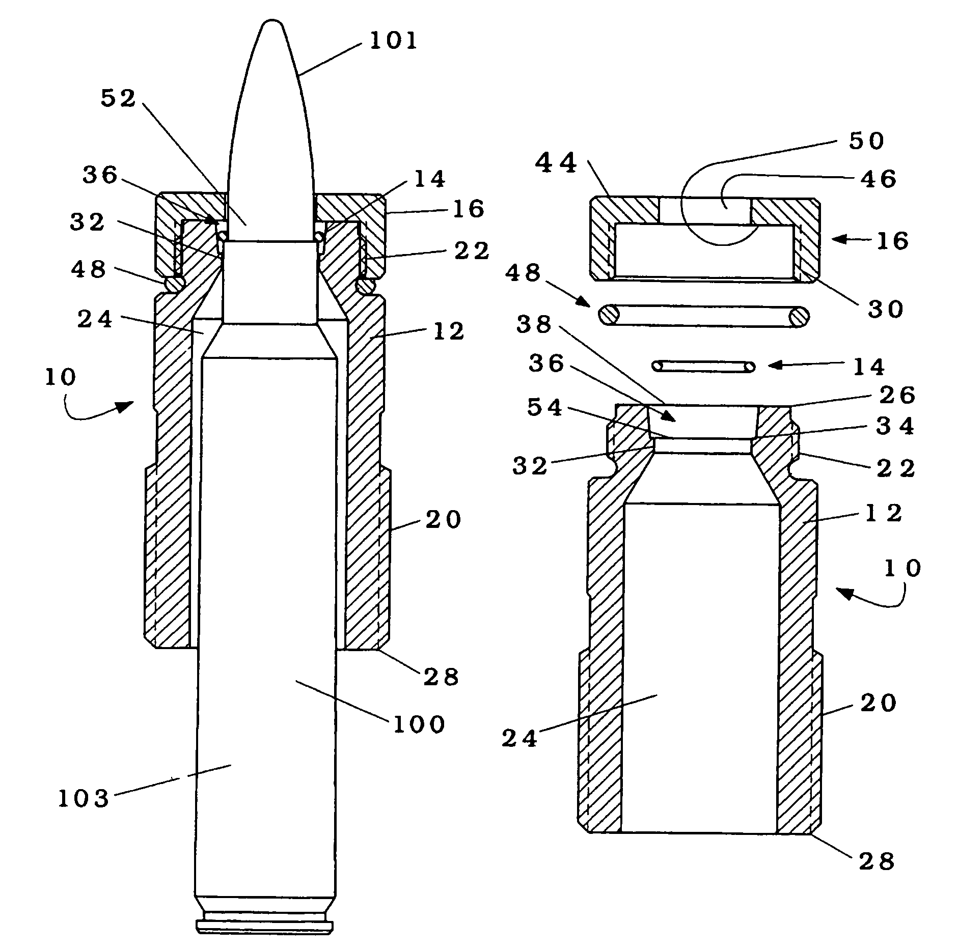
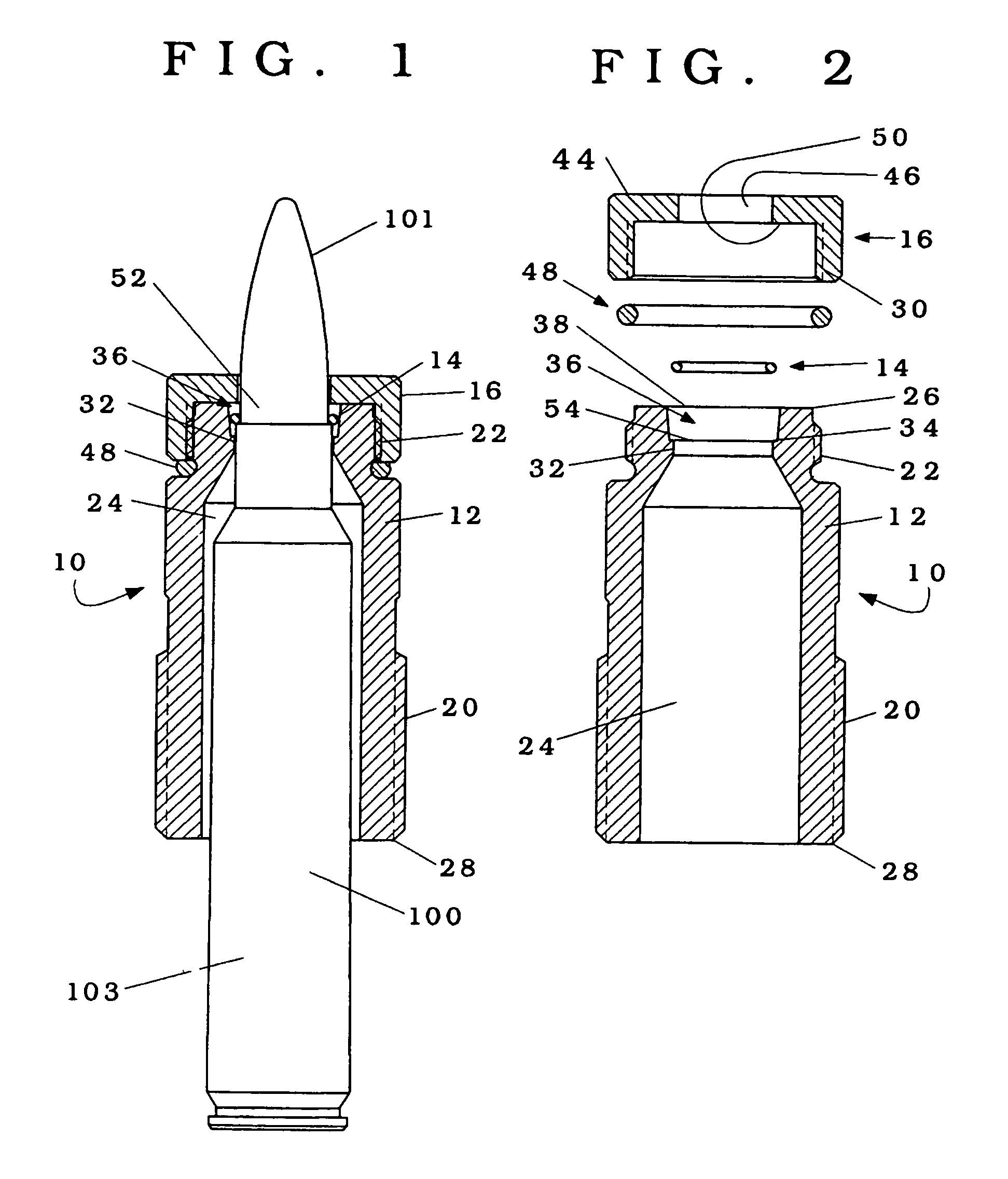
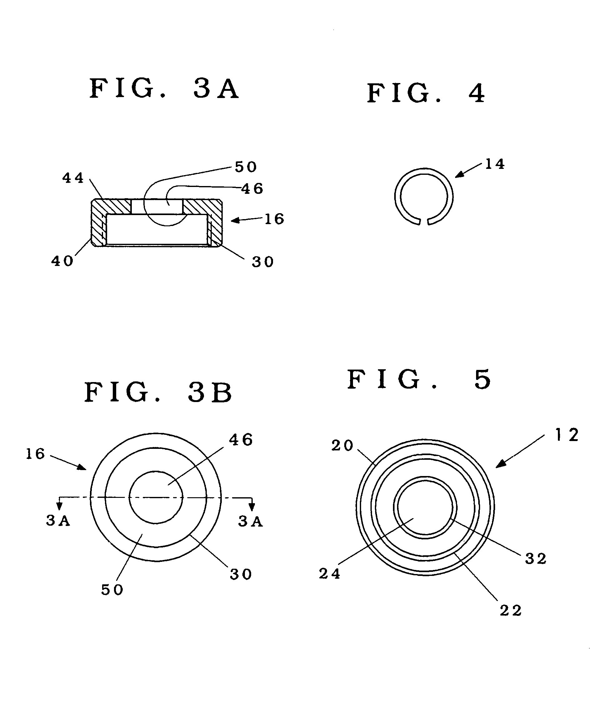
[0006]The device of the present invention constitutes a tool for use with a typical ammunition reloading press having at least a tool mount and ram arm forcibly moveable towards and away from a mounted tool. The tool of the present invention includes a “C” shaped ring consisting of a flexible substance formed as an incomplete annulus that is captured within a chamber with slightly tapered walls. The chamber wall is annular and tapered to present an inverted frustaconical surface so that the chamber has a larger internal diameter at its upper end. A tool body supports the C ring and chamber and is adapted to be mounted on a typical reloading press. The tool body has a central bore into which an ammunition cartridge can be at least partially inserted to a point where the bullet shank, close to but not within the cartridge, enters the C ring, which is then located in the chamber. Below the conical chamber, the central bore narrows to a neck sized to allow passage of the bullet and a portion of the case neck. Above the conical chamber, a cap partially encloses the chamber, leaving a central opening through which the bullet may pass. The C ring is formed slightly smaller than the greatest diameter portion of the bullet to be removed with a shape that evenly contacts the surface of the bullet when the bullet is engaged by the C ring. The outer diameter of the C ring, when relaxed, is larger than the inside diameter of the cap opening and the inside diameter of the central bore neck so that the C ring is captured within the chamber when assembled. The entry of the nose of the bullet into the C ring initially forces the C ring upward until the C ring engages a shoulder that prevents further upward movement and then the continued upward movement of the bullet forces the C ring onto the bullet as the C ring flexes radially outwardly, increasing the C ring diameter t...

Problems solved by technology

Collet type devices are relatively complex and expensive to manufacture.
Simpler devices are available but are s...

Method used


Image

  • Device and method for pulling bullets from cartridges
  • Device and method for pulling bullets from cartridges
  • Device and method for pulling bullets from cartridges

Examples


Embodiment Construction

)

[0017]With reference to the Drawings wherein like numerals represent like parts throughout the Figures, a device of the present invention for separation of a bullet from the cartridge with which the bullet has previously been joined in the assembly of an ammunition cartridge is generally designated by numeral 10 in FIGS. 1, 2, and 6. Conventional or typical ammunition cartridges are shown in some of the drawings and designated by the numeral 100, comprising a bullet 101 and a cartridge case 103, the bullet 101 being installed in the neck of case 103, and a conventional ammunition reloading press is designated by the numeral 102.

[0018]Device 10 consists of a body member 12, a “C” ring 14, and a cap member 16 and is intended for use with reloading press 102 having a tool mount 104 and a ram arm 106 forcibly moveable towards and away from a mounted device 10 as shown in FIG. 6. Since the usual orientation of a reloading press uses an upward motion to advance the ram arm 106 toward a t...


PUM


Abstract

A device for use with an ammunition reloading press, the device uses a “C” shaped split ring that is captured within a chamber with a slightly tapered frustaconical wall into the smaller end of which the bullet portion of an ammunition round can be inserted to a point where the bullet enters the C ring with a friction fit and subsequent withdrawal of the ammunition cartridge by operation of the press draws the ring into the increasingly narrow wall, decreasing the diameter of the ring and forcing a tighter grip on the bullet, which is then separated from the cartridge by further withdrawal and is removable from the device through an opening at the larger end of the chamber.

Description

BACKGROUND OF THE INVENTION[0001]A. Field of Invention[0002]The present invention relates generally to devices used in ammunition loading or reloading and more particularly to a new and improved device and method for pulling or removing bullets from ammunition cartridges.[0003]B. Description of Related Art[0004]In the loading or reloading of ammunition cartridges, a bullet is inserted into a cartridge and secured therein, generally by crimping the cartridge neck to the shank of the bullet securely enough that the bullet will not inadvertently separate from the cartridge, but will be separated by the explosive force of the charge when fired. It is occasionally desirable to separate a bullet from a cartridge into which the bullet has been inserted and secured, to salvage the components or prepare for reloading. Since the assembled ammunition represents a live round it must be handled with care to avoid accidents. Past tools for this purpose such as those shown in U.S. Pat. No. 3,174,3...

Claims


Application Information

Patent Timeline
IPC IPC(8): F42B33/06
CPCF42B33/06
Inventor LEE, RICHARD J.
Owner LEE RICHARD J
Why Eureka
Try Eureka