Dual flange tee

a dual-flange, tee technology, applied in the field of tees, can solve the problems of weakened sealing in those regions and inability to easily remove the hopper, and achieve the effect of facilitating opening and low profil

Inactive Publication Date: 2009-08-04
BRAY INT INC
View PDF16 Cites 16 Cited by
  • Summary
  • Abstract
  • Description
  • Claims
  • Application Information

AI Technical Summary

Benefits of technology

[0010]As a result, an advantage of the present invention is that in the event of clogging or blocking of the hopper fitting, or damage thereto, it can be separately removed from a hopper and replaced, while the valve remains securely mounted on the hopper so as to be capable of preventing flow through the discharge outlet thereof.
[0011]As another advantage, the dual flange fitting of the invention can have a lower profile compared to known standard hopper tees and other fittings, yet it facilitates opening of the valve or valve assembly thereof without the valve member being disposed in a path of flow through the lower hollow pipe section of the fitting.

Problems solved by technology

A disadvantage of many of the known hopper tee and other fitting constructions is that, particularly when used with a valve, they have a substantial downward extent beneath the hopper section, so as to be subject to potential damage from contact with road hazards, particularly railroad tracks and curbs, which the hoppers cross from time to time.
And, another disadvantage of the known hopper tees is that if they become damaged, or otherwise are rendered inoperable, for instance, such as due to blockage therein, or the like, they cannot be easily removed from the hopper, without either removing the valve or separately securing the valve to the hopper.
Possible shortcomings or disadvantages of the Sisk low profile tee include that, in the event it is required or desired to remove the tee, for instance, due to damage or clogging, the valve must also be removed, or connected in some manner to the hopper separately from the tee.
Additionally, when used with a butterfly type valve, the low profile design may result in a lower portion of the valve member being disposed in the horizontal flow path through the tee so as to possibly interfere with material flow therethrough.
Further, it is observed that the disclosed embodiments of the Sisk low profile tee do not include bolt holes through the portions of the flange located directly above the horizontal pipe section, which could possibly lead to weakened sealing in those regions.

Method used


Image

  • Dual flange tee
  • Dual flange tee
  • Dual flange tee

Examples


Embodiment Construction

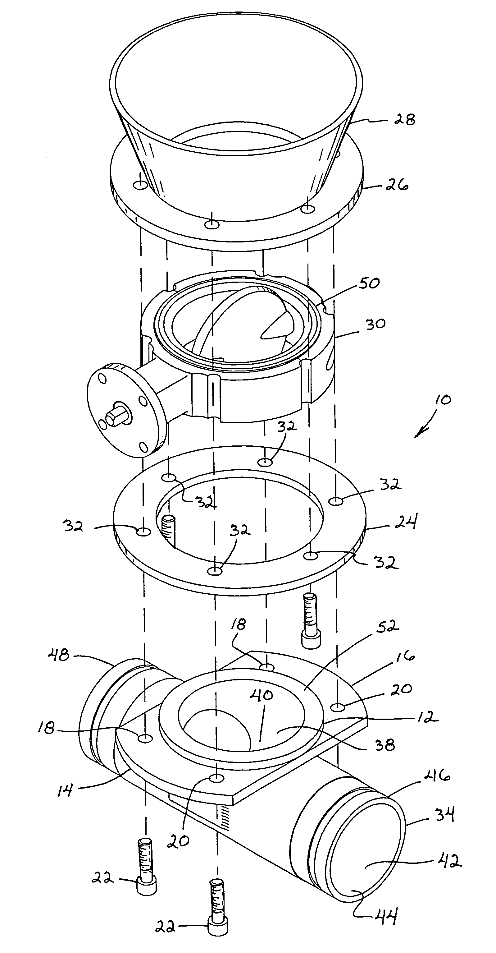
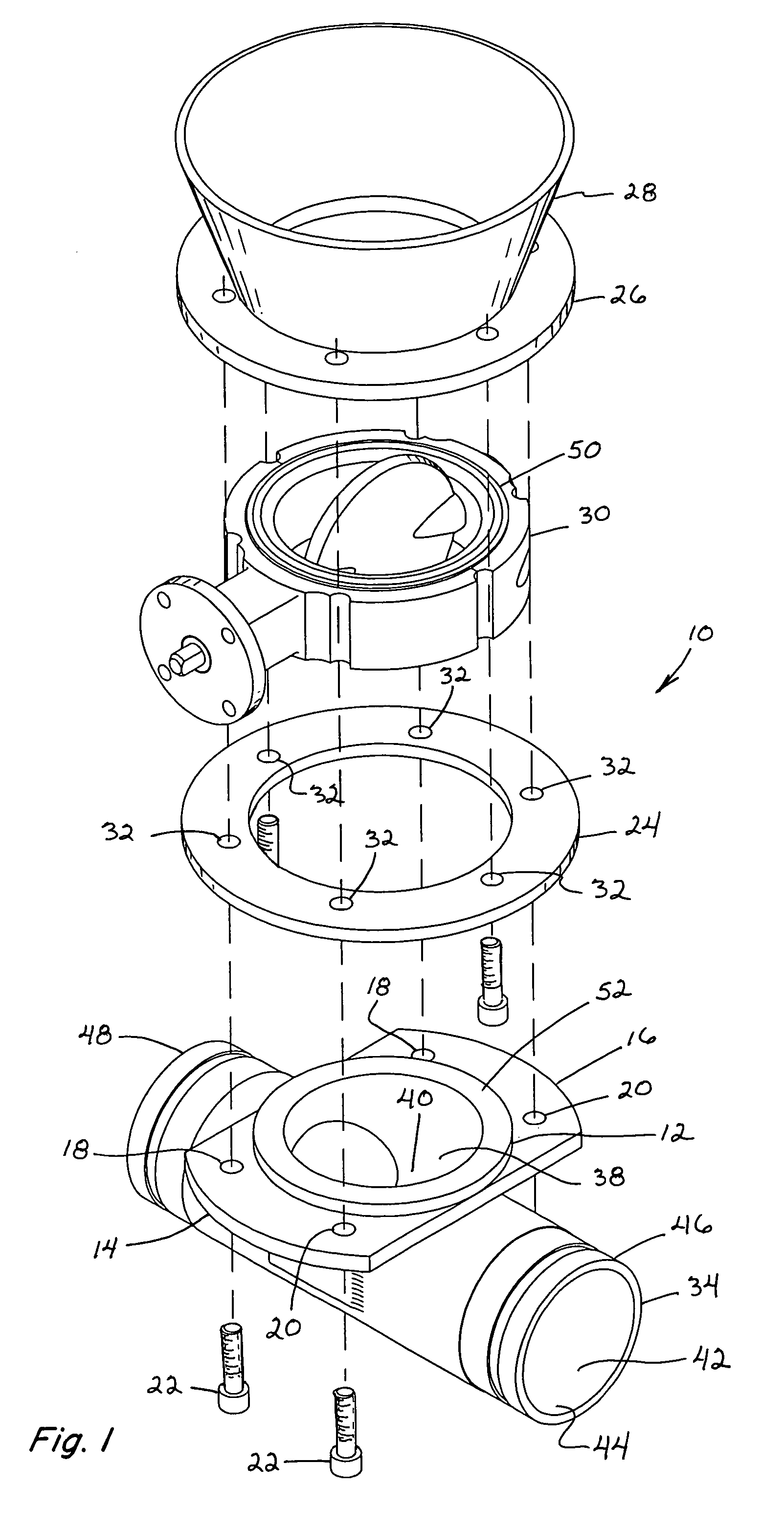
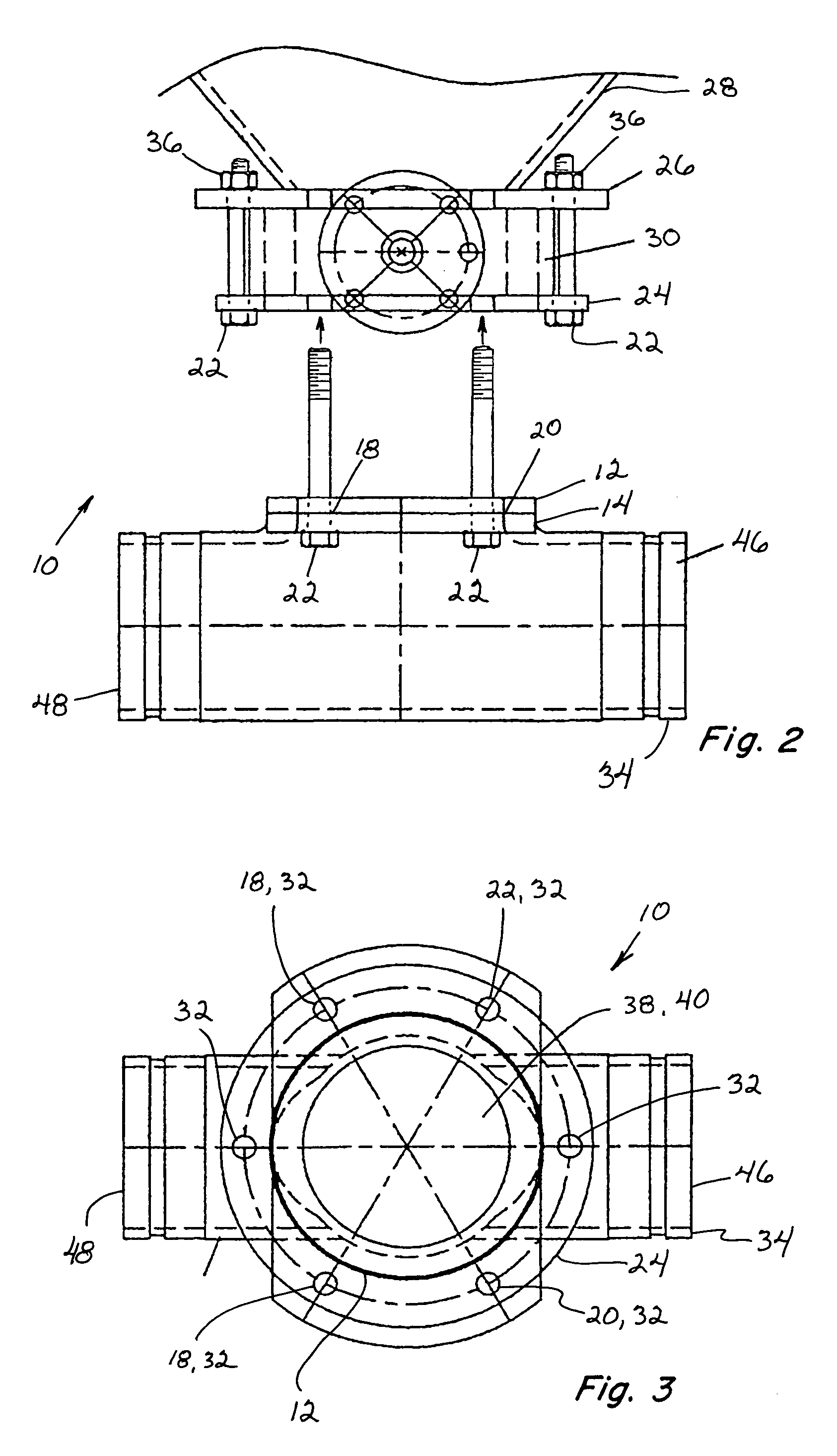
[0019]Referring now to the drawings, FIGS. 1, 2, 3, 4 and 5, a preferred dual flange tee 10 constructed and operable according to the teachings of the present invention is shown. The dual flange tee 10, in pertinent part, includes a vertical upper hollow pipe section 12 having sidewardly extending wings 14 and 16 at the upper extent of the section. Each of the wings 14 and 16 includes holes 18 and 20 therethrough for receiving a plurality of fasteners, such as conventional bolts 22 therethrough, for attachment to a lower ring 24, which can also be referred to also as a loose flange, which mounts to a bottom flange 26 extending around a discharge outlet of hopper 28. Bottom flange 26 of the hopper 28 includes an array of vertical holes therethrough at spaced locations therearound adapted for receiving fasteners such as bolts 22 therein for holding objects thereto. The lower ring 24 or loose flange is configured to cooperate with and to support or hold a valve 30 in place under the bo...


PUM


Abstract

The dual flange hopper tee or other fitting connects to the bottom of a hopper for use in unloading the contents thereof, and has a relatively low profile for ground clearance. When used in conjunction with a valve, the tee or other fitting can be removed from the hopper without requiring removal of the valve, and can allow opening of the valve without interfering with flow through a horizontal pipe section of the fitting.

Description

[0001]This application claims the benefit of U.S. Provisional Application No. 60 / 619,165, filed Oct. 15, 2004.TECHNICAL FIELD[0002]This invention relates generally to a tee or other fitting for connection to the bottom of a hopper for use in unloading the contents thereof, and more particularly, to a dual flange tee or other fitting which provides improved ground clearance compared to many prior known tee and fitting constructions, and when used in conjunction with a valve, allows the tee to be removed from the hopper without requiring removal of the valve, and can allow opening of the valve without interfering with flow through a horizontal pipe section of the fitting.BACKGROUND ART[0003]Commonly, mobile hopper trailers and vehicles are used for carrying bulk commodities such as industrial products such as pelletized plastics and the like, and food products such as milled flours and the like. Typically, the hoppers include multiple sections or compartments for receiving and holding...

Claims


Application Information

Patent Timeline
Patent Type & Authority Patents(United States)
IPC IPC(8): F16K51/00
CPCF16L41/16Y10T137/7504
Inventor KRAENZLE, DAVID G.
Owner BRAY INT INC
Why Eureka
Try Eureka