Motor vehicle lock

a technology for motor vehicles and locks, applied in the direction of passenger lock actuation, carpet fasteners, lock applications, etc., can solve the problems of changing the installation situation of such a motor vehicle lock, affecting the safety of passengers, and implementing the decoupled position of the actuation chain, so as to reduce the cost

Inactive Publication Date: 2009-08-04
BROSE SCHLIESSSYSTEME GMBH & CO KG
View PDF16 Cites 27 Cited by
  • Summary
  • Abstract
  • Description
  • Claims
  • Application Information

AI Technical Summary

Benefits of technology

[0013]A primary object of this invention is to devise a motor vehicle lock which enables optimized actuation of different operating state and in doing so reduces costs.

Problems solved by technology

Thus, the installation situation of such a motor vehicle lock changes.
Sensors are necessary for defined reaching of the individual positions, for which reason the control is relatively complex.
Furthermore, it is disadvantageous that the decoupled position of the actuation chains is implemented by one spring at a time.
However, springs are complex to install, and moreover, are relatively susceptible to faults.
Furthermore, in practice, it has been shown that linearly movable elements of the actuation chains are not feasible over the long term.
Wear and corrosion are difficult to handle there.
However, when the outside door handle in the CL operating state is actuated so quickly that the central locking drive cannot move the control means fast enough into the UL operating state, the central locking drive assumes the opening function.
The use of two different ranges of motion for the different functions is unfavorable in this respect since, in this way, an altogether relatively large range of motion is necessary.
Accordingly, the transmission element must be made accordingly large and a correspondingly large installation space is necessary.

Method used


Image

  • Motor vehicle lock
  • Motor vehicle lock
  • Motor vehicle lock

Examples


Embodiment Construction

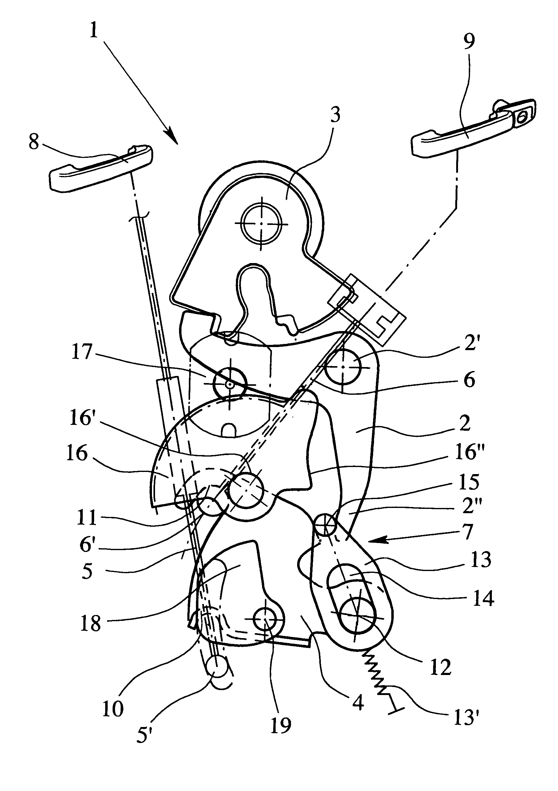
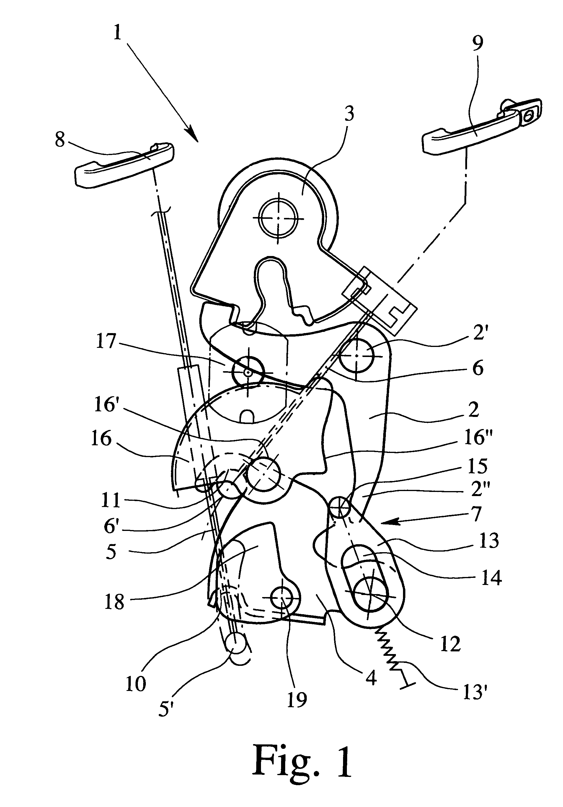
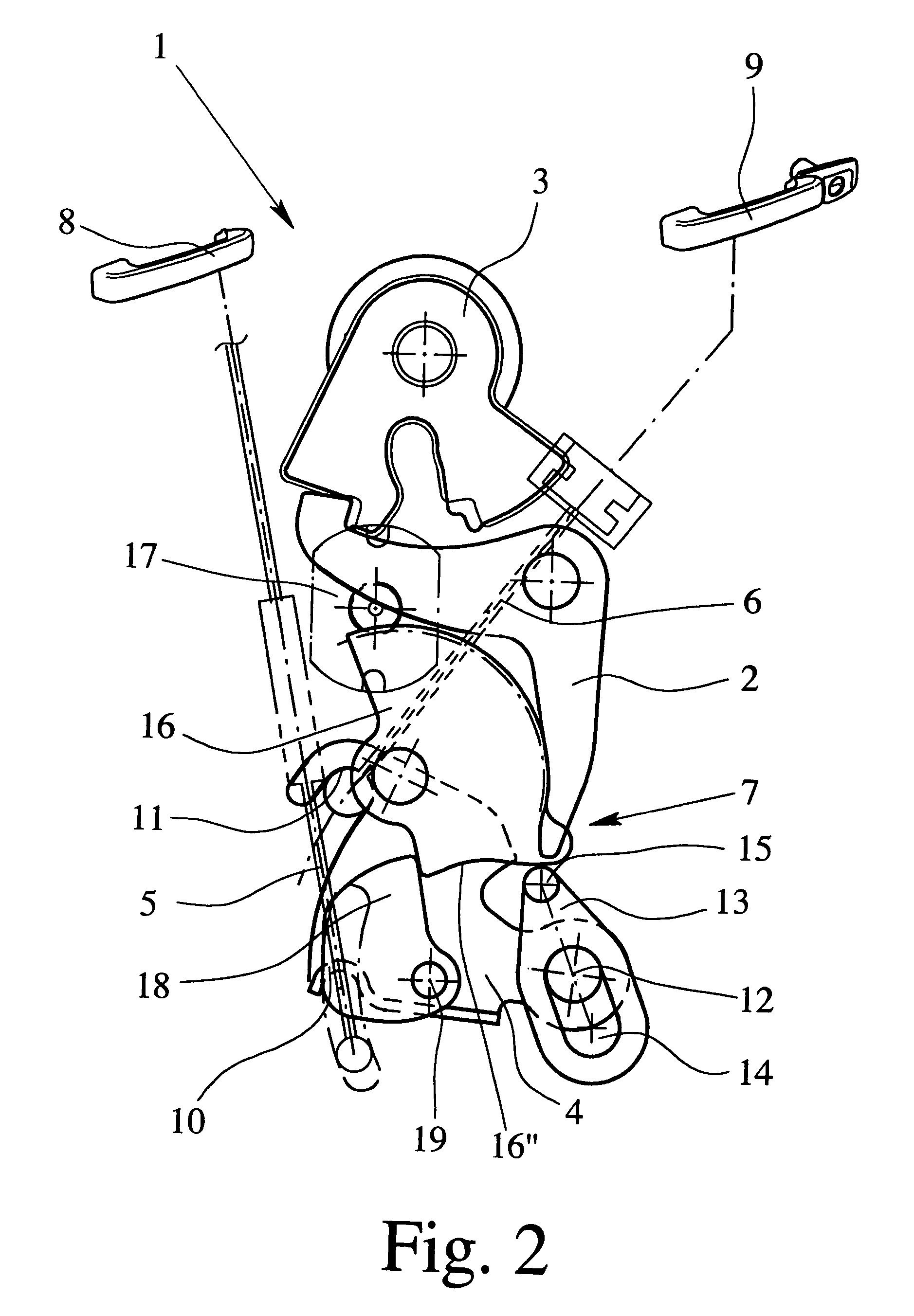
[0053]In the figures, the same reference numbers are used for the same or similar parts. This is intended to indicate that the corresponding or comparable properties and advantages are achieved even if a repeated description of these parts is omitted. If in the drawings overlapping of components occurs which functionally seems to contradict the described sequences, it must be considered that the elements can be located in different planes. Collisions are therefore present only in the drawings, not in reality.

[0054]FIG. 1 shows a view of a motor vehicle lock with a ratchet 2 and a latch 3. The ratchet 2 has an engaged position (FIG. 1) in which it keeps the latch 3 in the closed position. In addition, the ratchet 2 has a raised position (not shown) that can be reached by swivelling counterclockwise the ratchet 2 around the pivot pin 2′, for example, influenced by the application of force of the actuation arm 2″ (to the right in FIG. 1) in which the latch 3 is released.

[0055]Furthermo...


PUM


Abstract

Motor vehicle lock with a ratchet, latch, actuation lever, internal actuation chain, external actuation chain and a control, the ratchet having an engagement position in which it holds the latch in the closed position, and a raised position in which the latch is released, the ratchet being movable from the engagement position into the raised position by the actuating lever, the control having different operating states and depending on the state, the ratchet is actuatable via the actuation lever by the internal actuation chain from an inside door handle and / or by the external actuation chain from an outside door handle or not at all. In the base state, the internal actuation chain and the external actuation chain are coupled to the actuation lever and the internal actuation chain and / or the external actuation chain can be decoupled from the actuation lever by the control depending on the operating state.

Description

BACKGROUND OF THE INVENTION[0001]1. Field of Invention[0002]This invention relates to a motor vehicle lock. The motor vehicle lock is especially suited as a side door lock, but can also be used for other motor vehicle locks which have at least two actuation chains.[0003]2. Description of Related Art[0004]The concept “actuation chain” quite generally designates a chain of action of forces between a first actuation element, such as a door handle, for example, and a second actuation element, such as, ultimately, a ratchet.[0005]For motor vehicle locks, especially those for side doors of motor vehicles, providing two actuation chains from the outside door handle and the inside door handle to the ratchet is known. In a classic version of such a motor vehicle lock (German Patent Application DE 195 19 010 A1 and corresponding U.S. Pat. No. 5,921,595) the two actuation chains each have lever arrangements which are independent of one another and which act on the ratchet itself or on an actua...

Claims


Application Information

Patent Timeline
Patent Type & Authority Patents(United States)
IPC IPC(8): E05C3/16E05B47/00E05B65/12E05B65/20E05C3/06
CPCE05B81/06E05B81/14E05B77/28E05B81/16E05B77/26E05B81/62Y10S292/23Y10T292/1047Y10T292/1082
Inventor BROSE, SIMONKACHOUH, CHECRALLAH
Owner BROSE SCHLIESSSYSTEME GMBH & CO KG
Why Eureka
Try Eureka