
Connector for connecting printed boards having a plug having press-in grooves fitted into a socket

a technology of connecting printed boards and sockets, which is applied in the direction of coupling device connections, coupling contact members, coupling device details, etc., can solve the problems of reducing contact reliability, increasing contact resistance, and difficult fitting work, so as to achieve the effect of preventing coming off and further improving contact reliability

Inactive Publication Date: 2009-08-04
ORMON CORP
View PDF10 Cites 33 Cited by
  • Summary
  • Abstract
  • Description
  • Claims
  • Application Information

AI Technical Summary

Benefits of technology

[0006]In view of the foregoing, an object of the present invention is to provide a connector with high contact reliability even if component accuracy or assembly accuracy varies.
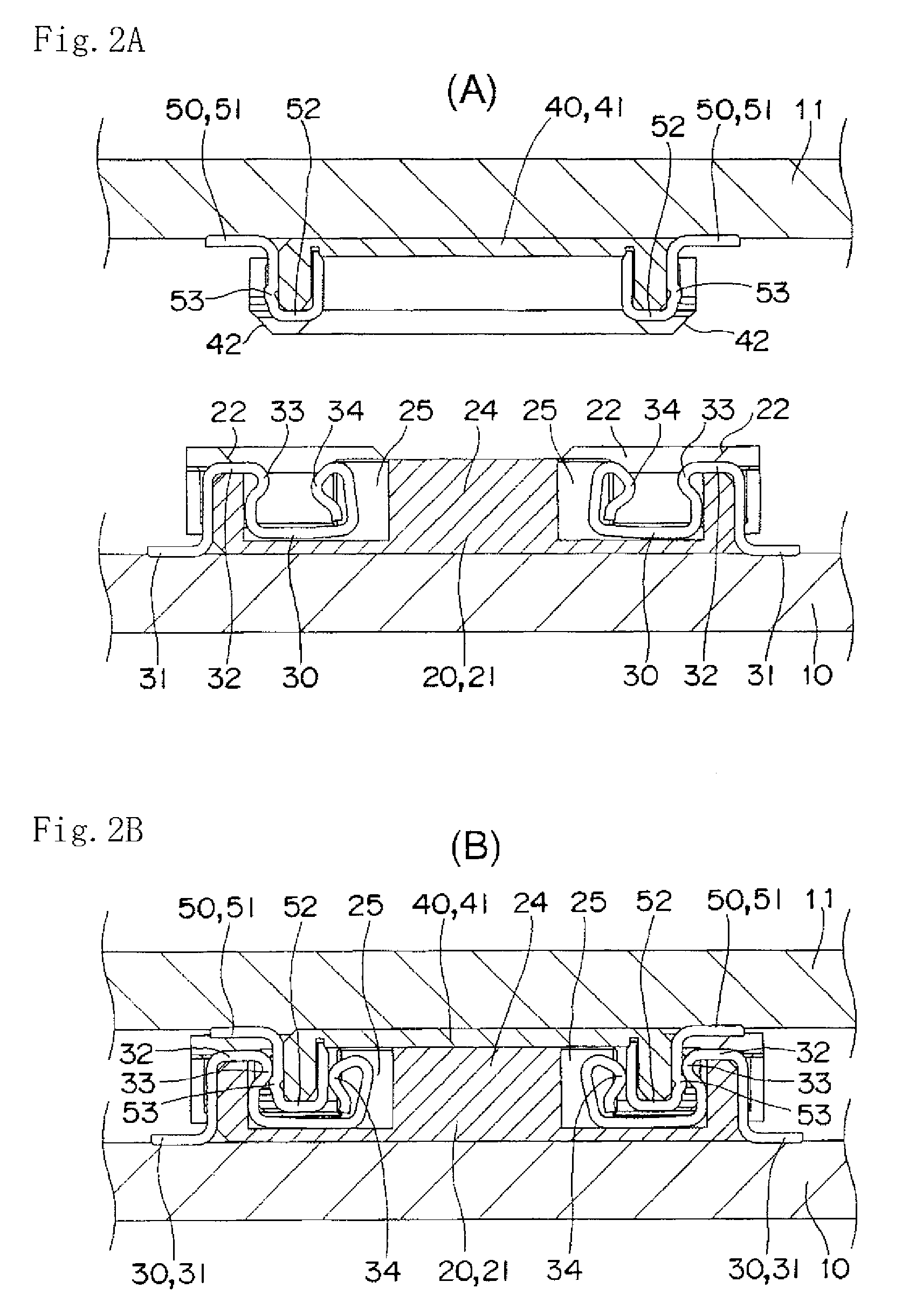
[0008]According to the aspect of the present invention, the first splice is fitted in the press-in groove of the plug, and the first splice is brought into elastic contact with the second splice which is press-fitted and retained in the press-in groove, whereby the electrical connection is established between the first splice and the second splice. Therefore, even if the component accuracy and assembly accuracy vary, the first splice whose position is regulated in the press-in groove is correctly brought into elastic contact with the second splice. Accordingly, the connector with high contact reliability with which the contact failure hardly occurs is obtained.
[0010]In the connector according to the aspect of the present invention, a second contact portion provided in a free end portion of the first splice is preferably brought into elastic contact with a rear surface of a U-shaped press-in portion of the second splice press-fitted in the press-in groove of the plug. Therefore, the second contact portion of the first splice is brought into elastic contact with the rear surface of the U-shaped press-in portion of the second splice, so that not only the second contact portion of the first splice is brought into elastic contact with the U-shaped press-in portion of the second splice, but also the first contact portion of the first splice is more surely brought into elastic contact with the second splice. Accordingly, the contact reliability is further improved between the first splice and the second splice.
[0011]In the connector according to the aspect of the present invention, retaining protrusions are preferably provided on both outside surfaces of the U-shaped press-in portion of the second splice, the retaining protrusions being latched onto at least one of the first contact portion and the second contact portion, the second splice being press-fitted between the first contact portion and the second contact portion in the first splice, the first contact portion and the second contact portion facing each other. Therefore, when the first splice is brought into elastic contact with the second splice, the first splice and the second splice are brought into elastic contact with each other while overriding the retaining protrusion. Accordingly, there is an advantage that click feeling is obtained which gives a sense of reassurance to a worker while the coming off can be prevented.

Problems solved by technology

Therefore, the positioning is not easily performed in the fitting work.
When the header is forcedly connected to the socket while inaccurately positioned, there arises a problem that contact resistance is increased and contact reliability is thus lowered.

Method used


Image

  • Connector for connecting printed boards having a plug having press-in grooves fitted into a socket
  • Connector for connecting printed boards having a plug having press-in grooves fitted into a socket
  • Connector for connecting printed boards having a plug having press-in grooves fitted into a socket

Examples


Embodiment Construction

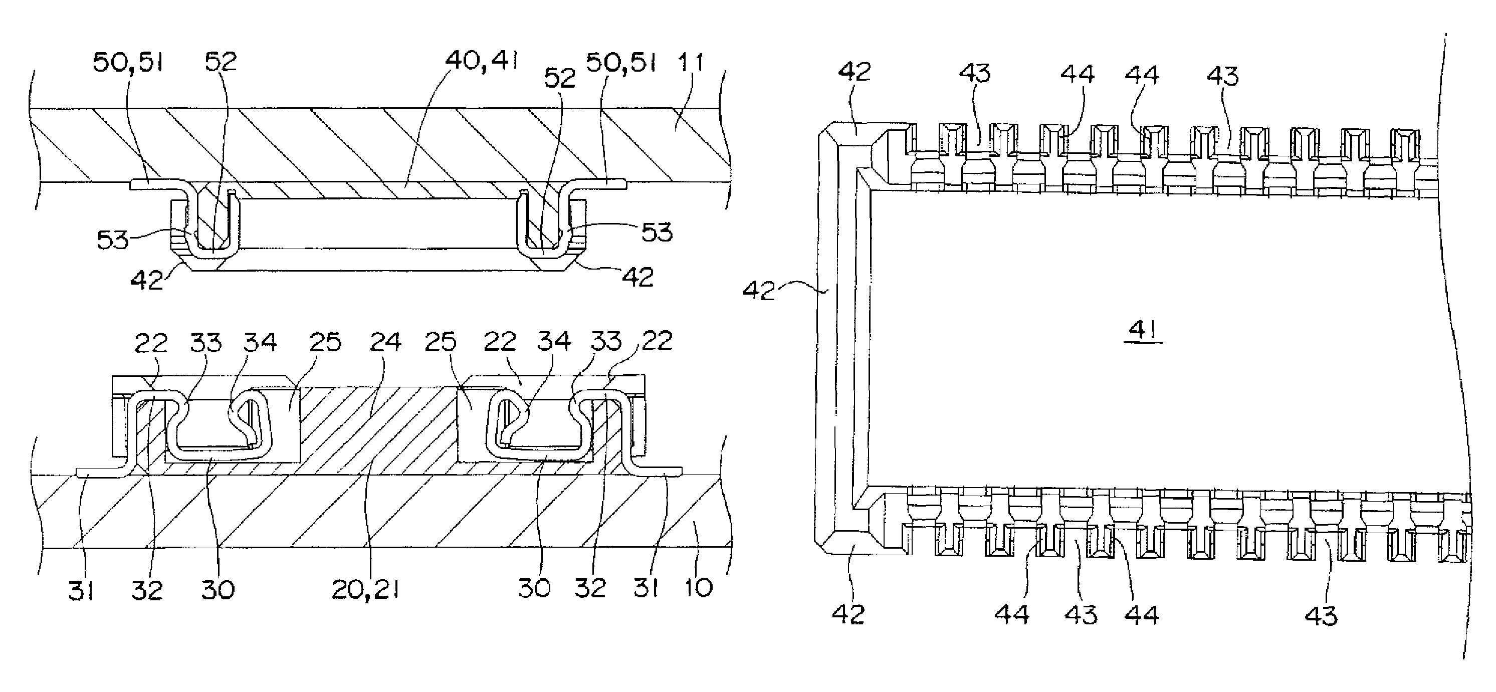
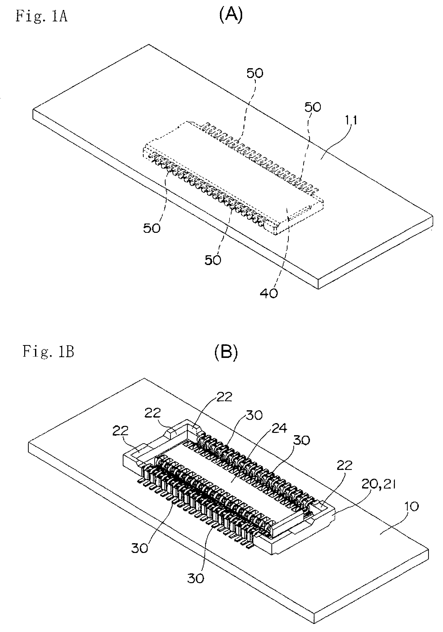
[0026]Preferred embodiments of a connector according to the present invention will be described with reference to the accompanying drawings. As shown in FIGS. 1 and 2, the connector according to the present embodiment includes a socket 20 and a plug 40. The socket 20 is connected to an upper surface of a printed wiring board 10, and the plug 40 is connected to a lower surface of a printed wiring board 11.

[0027]In the socket 20, a plurality of first splices 30 are provided in parallel along opening edge portions located on opposite sides of a socket body 21. As shown in FIG. 6, the socket body 21 has a box shape with a shallow bottom, a guiding tapered surface 22 is formed in the opening edge portion of the socket body 21, and press-in grooves 23 are provided in parallel at a predetermined pitch along outside surfaces of sidewalls located on opposite sides. The first splices 30 to be described later are press-fitted in the press-in grooves 23. In the socket body 21, a base portion 24...


PUM


Abstract

A connector includes a socket in which a plurality of first splices are provided in parallel in an opening edge portion and a plug which has a flat shape. The plug is capable of being fitted in the opening edge portion of the socket. The plug includes a plurality of second splices press-fitted in press-in grooves provided in parallel at positions corresponding to the first splices in the plug. Each of the first splices is fitted and abuts on an inside surface of one of the press-in grooves. Each of the first splices is brought into elastic contact wit one of the second splices to establish electrical connection.

Description

BACKGROUND OF THE INVENTION[0001]1. Field of the Invention[0002]The present invention relates to a connector, particularly to a connector for electrically connecting printed boards to each other.[0003]2. Description of the Related Art[0004]Conventionally, in a connector which connects printed boards to each other, a socket 11 fixedly connected to an upper surface of a circuit board A is fitted in a header 12 fixedly connected to a lower surface of another printed board A, and a contact terminal 14 provided in the socket 11 and a contact terminal 16 provided in the header 12 are connected to each other while being in elastic contact with each other (refer to, for example, Japanese Patent Application Laid-Open No. 2005-203139).[0005]However, in the conventional connector, when the header 12 is positioned and fitted in the socket 11, the connector is not visible because the connector is hidden behind the upper printed board. Therefore, the positioning is not easily performed in the fit...

Claims


Application Information

Patent Timeline
Patent Type & Authority Patents(United States)
IPC IPC(8): H01R12/00
CPCH01R12/716H01R13/20H01R12/73H01R12/71
Inventor HOSHINO, HIROKAZUKIMURA, NAOYUKISHIMURA, YUSUKE
Owner ORMON CORP
Learn More