Device for removing consumable analytic products from a storage container

Inactive Publication Date: 2009-08-04
ROCHE DIAGNOSTICS GMBH
View PDF28 Cites 11 Cited by
  • Summary
  • Abstract
  • Description
  • Claims
  • Application Information

AI Technical Summary

Benefits of technology

[0026]In addition, the removal of a consumable analytic product can be advantageously improved by increasing the thrusting force during at least one of the following operational conditions: when the plunger penetrates through the foil covering the insertion opening, when the consumable product penetrates through the foil covering the removal opening, when positioning the removed consumable product into a predetermined working position, or when expelling a used consumable product out of a predetermined working position.
[0027]In this context, a working position is any predetermined, defined position which a consumable product must assume for its intended use, e.g. the location of a sample receptacle or a position in which an analytic measurement is carried out. The consumable product must normally be precisely positioned at such working positions so that corresponding guides or abutment elements are provided leading to an increase in the thrusting force needed to transport the consumable product. In general, the device in accordance with the invention can effect increased thrusting forces required in those regions in which increased load occurs, e.g. in the above mentioned positions, whereas the thrusting force can be lower in other regions along the forward path of the plunger. In particular, energy consumption is minimized, since an increased thrusting force is provided only in those regions where the plunger must overcome increased load.
[0028]In accordance with an additional preferred feature, the device is configured in such a fashion that the thrusting speed of the plunger is reduced in regions having increased thrusting force and increased in regions having reduced thrusting force. Using this rule, the overall transport time for removal of the consumable product can be particularly well optimized while taking into consideration the associated energy consumption.
[0029]A desired thrusting force-thrusting path dependence can, in principle, be realized using purely electronic means, wherein the thrusting motion of the plunger is controlled by

Problems solved by technology

The choice of materials and thickness of the foils which are used to seal the openings in the storage container chambers is limited by two requirements.
On the other hand, the foil cannot be too strong, since it must be ruptured by the plunger or by the consumable analytic product using the pressure imparted by the thrusting force of the plunger.
However, according to prior art, an actual optimal solution can not be achieved, since the drive is over-dimensioned through long stretches of the consumable product forward path, since it is configured for the maximum occurrin

Method used


Image

  • Device for removing consumable analytic products from a storage container
  • Device for removing consumable analytic products from a storage container
  • Device for removing consumable analytic products from a storage container

Examples


Example

DETAILED DESCRIPTION OF THE DRAWINGS

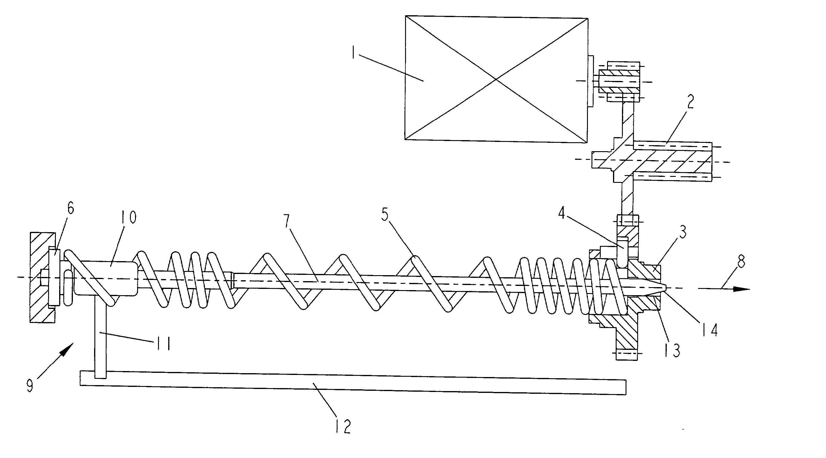
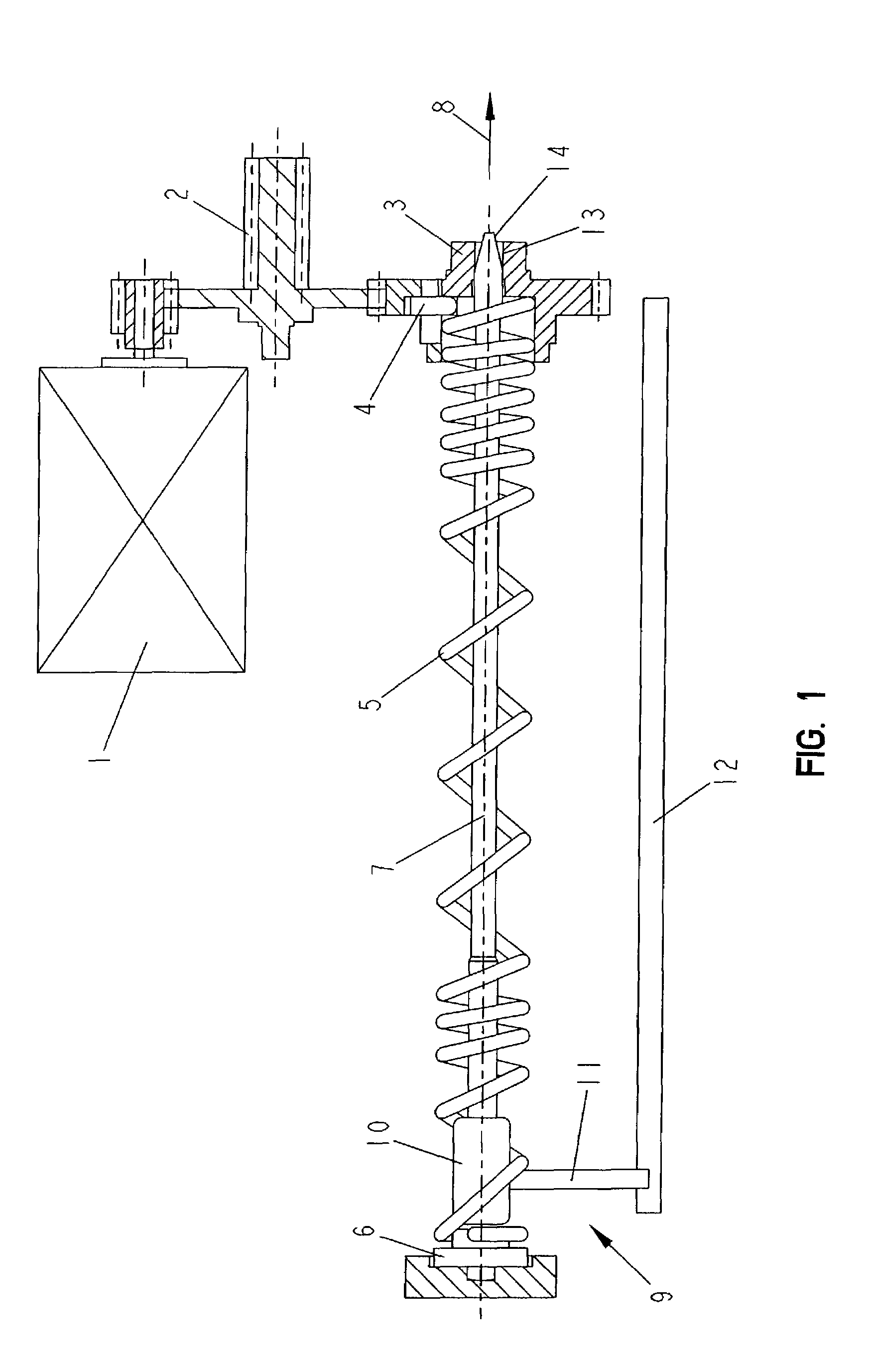
[0052]FIG. 1 shows a preferred embodiment of a device in accordance with the invention for the removal of a consumable analytic product from a storage container (not shown in FIG. 1), which realizes the concept in accordance with the invention of a position dependent thrusting force via a mechanical path control, and is advantageous for use in very small, battery driven analytic apparatus. The device includes an electric drive motor 1, the drive force of which is transmitted by means of a transmission 2 onto a drive wheel 3. The carrier peg 4 of a cylindrical helically wound transport spiral 5 is connected to the drive wheel 3 for secure rotation therewith. The transport spiral 5 is borne for rotation at its other end in a rotation bearing 6 and can be set into rotation about its longitudinal axis by the drive.

[0053]The transport spiral 5 serves as a control element of a path control and has sections with differing pitch. It consists primarily of ...


PUM


Abstract

A method and a device for removing an analytic consumable product, in particular a test element, from a storage container having chambers which are sealed by foils from which the consumable product is pushed out by means of a plunger (7) can be optimized in that the magnitude of the thrusting force exercised by the plunger (7) during its forward motion can be controlled in dependence on the plunger (7) position.

Description

CROSS REFERENCE TO RELATED APPLICATIONS[0001]This application is a divisional of U.S. patent application Ser. No. 09 / 489,502, filed on Jan. 21, 2000 now U.S. Pat. No. 6,475,436, which claims priority to DE 199 02 601.7, filed Jan. 23, 1999.BACKGROUND AND SUMMARY OF THE INVENTION[0002]The invention concerns a device and a corresponding method for removing a consumable analytic product, in particular a test element, from a storage container having one or more chambers. The chambers each contain one or more consumable products and each have a removal opening for removal of a consumable product and an insertion opening lying across from the removal opening for the introduction of a plunger to transport the consumable product being removed. The removal opening and the insertion opening are each sealed with a foil (also designated as a sealing foil) for storing the consumable product. In order to remove a consumable product, a plunger is displaced by a drive unit and the consumable produc...

Claims


Application Information

Patent Timeline
IPC IPC(8): G01N35/10G01N35/04B01L99/00G01N33/487G01N35/00
CPCB01L99/00G01N33/48757G01N2035/00039Y10T436/2575Y10T436/114165Y10T436/11Y10T436/112499G01N2035/00089
Inventor SCHABBACH, MICHAELMILTNER, KARLKLEMM, THOMASBAUMANN, ROLFDILGER, MEINRAD
Owner ROCHE DIAGNOSTICS GMBH
Why Eureka
Try Eureka