Loudspeakers

a loudspeaker and wave panel technology, applied in the direction of diaphragm construction, electromechanical transducer, transducer diaphragm, etc., can solve the problems of limiting the useful sound output to 250 hz for display systems of the highest, direct control of these environmental conditions, etc., to achieve the effect of improving the low frequency capability of the device, reducing the visibility of vibration, and improving the useful low frequency bandwidth

Active Publication Date: 2009-08-04
GOOGLE LLC
View PDF9 Cites 34 Cited by
  • Summary
  • Abstract
  • Description
  • Claims
  • Application Information

AI Technical Summary

Benefits of technology

[0026]The outcome is improved useful low frequency bandwidth from the device. Firstly the low frequency capability of the device is improved, due to the larger volume per unit area behind the second portion. Secondly, the concentration of low frequency energy away from the screen area minimizes the visibility of vibration at low frequencies, and the full capability of the system is used without being prematurely limited by such visual effects. The surface of the second portion may also be designed to minimize visual vibration, e.g. a matt surface finish.

Problems solved by technology

1. The low frequency limit for useful radiation from the plate is determined by the gap between the plate and the screen. The cavity formed behaves as a distributed compliance, which together with the areal density of the plate forms a mass spring resonance. Below this resonance frequency the modes excited in the plate radiate only weakly, whereas above this frequency useful modal radiation may be achieved, and
2. A second parameter that controls the effective low frequency limit for the system is the visibility of vibrations on the plate. For a high quality visual display visual vibration can be unacceptable. The most dominant effect is the visibility of reflections from the plate, rather than any disturbance of the direct image of the screen. This may be minimized with control over the environment in which the unit is used, such as lowering the light level in the room, or angling the screen to minimize the visibility of reflections from light sources in the room. Anti-reflection coatings on the plate may improve the performance. In many applications, however, there is no direct control over these environmental factors, and this problem can be severe.
This limits the useful sound output to ˜250 Hz for display systems of the highest quality.

Method used


Image

  • Loudspeakers
  • Loudspeakers
  • Loudspeakers

Examples


Embodiment Construction

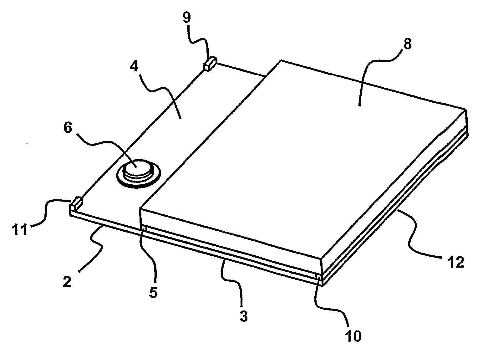
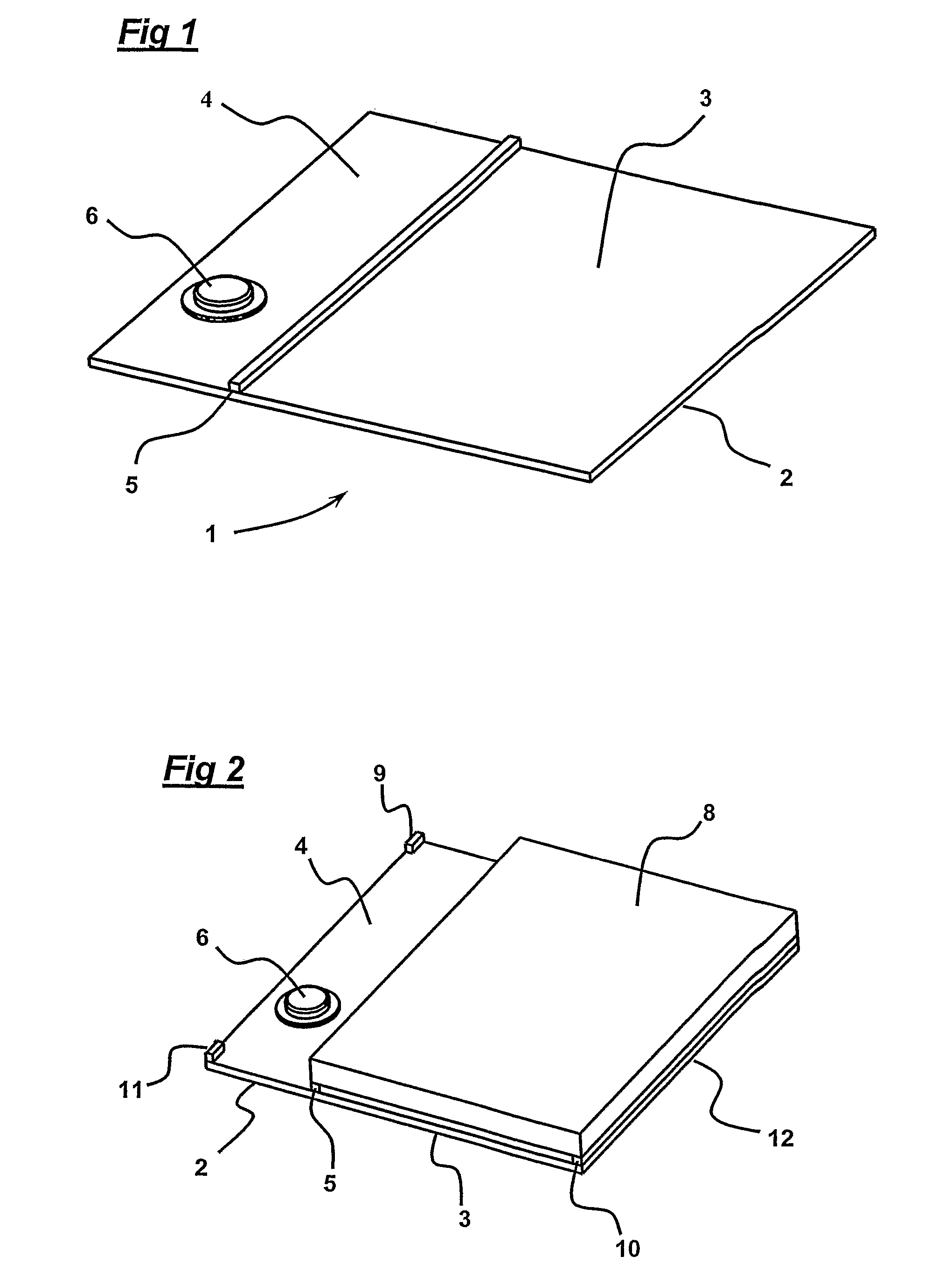
[0033]FIG. 1 shows a generally rectangular panel-form bending-wave loudspeaker (1) generally of the kind described in International Patent Application WO97 / 09842 and wherein the panel radiator (2) is divided into two portions or regions (3,4), that is a first portion or region 1 indicated by reference numeral (3) and a further portion or region 2 indicated by reference numeral (4), by a strip-like mechanical impedance divider (5) of a foam plastics material. The divider (5) extends across the panel from side to side such that region 2 is relatively small compared to region 1. A vibration exciter (6) is coupled to region 2 to apply bending wave energy thereto to cause the radiator to resonate and radiate an acoustic output in response to a signal applied to the exciter in the normal manner. However, in accordance with the invention, low frequency bending waves are confined to region 2 by the divider (5) and, as explained below, the nature of the divider is arranged to be such that hi...


PUM


Abstract

A loudspeaker comprising a bending wave panel-form acoustic radiator having a first portion and at least one further portion a transducer for exciting bending waves in the radiator, the transducer being coupled to the further portion of the radiator to cause the radiator to radiate an acoustic output, and means confining low frequency radiation to the further portion of the radiator.

Description

[0001]This application claims the benefit of U.S. provisional application No. 60 / 558,103, filed Apr. 1, 2004.TECHNICAL FIELD[0002]This invention relates to bending wave panel loudspeakers, and more particularly, but not exclusively to such loudspeakers combined with visual display screens.BACKGROUND ART[0003]International Application WO 00 / 02417 describes a loudspeaker comprising a visual display screen, a panel-form member positioned adjacent to the display screen and at least a portion of which is transparent and through which the display screen is visible, and a vibration exciting transducer mounted to an edge or marginal portion of the panel-form member to apply energy to the panel-form member to cause the panel-form member to act as an acoustic radiator, characterized in that the panel-form member is arranged to be resonant at audio frequencies, in that the vibration transducer is adapted to apply bending wave energy to the panel-form member to cause it to resonate to act as an...

Claims


Application Information

Patent Timeline
Patent Type & Authority Patents(United States)
IPC IPC(8): H04R25/00H04R1/24H04R7/04H04R7/06
CPCH04R1/24H04R7/045H04R2499/15H04R2440/05H04R7/06H04R2430/00
Inventor WHITWELL, TIMOTHY CHRISTOPHERHILL, NICHOLAS PATRICK ROLANDBOYD, GEOFFREY ARTHUR COLERIDGE
Owner GOOGLE LLC
Why Eureka
Try Eureka