Morphological inspection method based on skeletonization

a skeletonization and morphological technology, applied in the direction of semiconductor/solid-state device testing/measurement, image enhancement, instruments, etc., can solve the problems of large computing source, large number of computing sources, and large number of skeletonization processes

Active Publication Date: 2009-08-04
CAMTEK LTD
View PDF3 Cites 5 Cited by
  • Summary
  • Abstract
  • Description
  • Claims
  • Application Information

AI Technical Summary

Problems solved by technology

Defects in the form of structural flaws, process residues, and external contamination occur during the production of objects such as Printed Circuit Boards, semiconductor wafers, artwork or reticles.
Unfortunately, people are relatively slow and are quickly fatigued by the highly-repetitive task of observing and characterizing defects.
Moreover, the skeletonization process requires a lot of computing source.
Consequently, the main disadvantage of these inspection systems is that they are complicated and expensive.

Method used


Image

  • Morphological inspection method based on skeletonization
  • Morphological inspection method based on skeletonization
  • Morphological inspection method based on skeletonization

Examples


Embodiment Construction

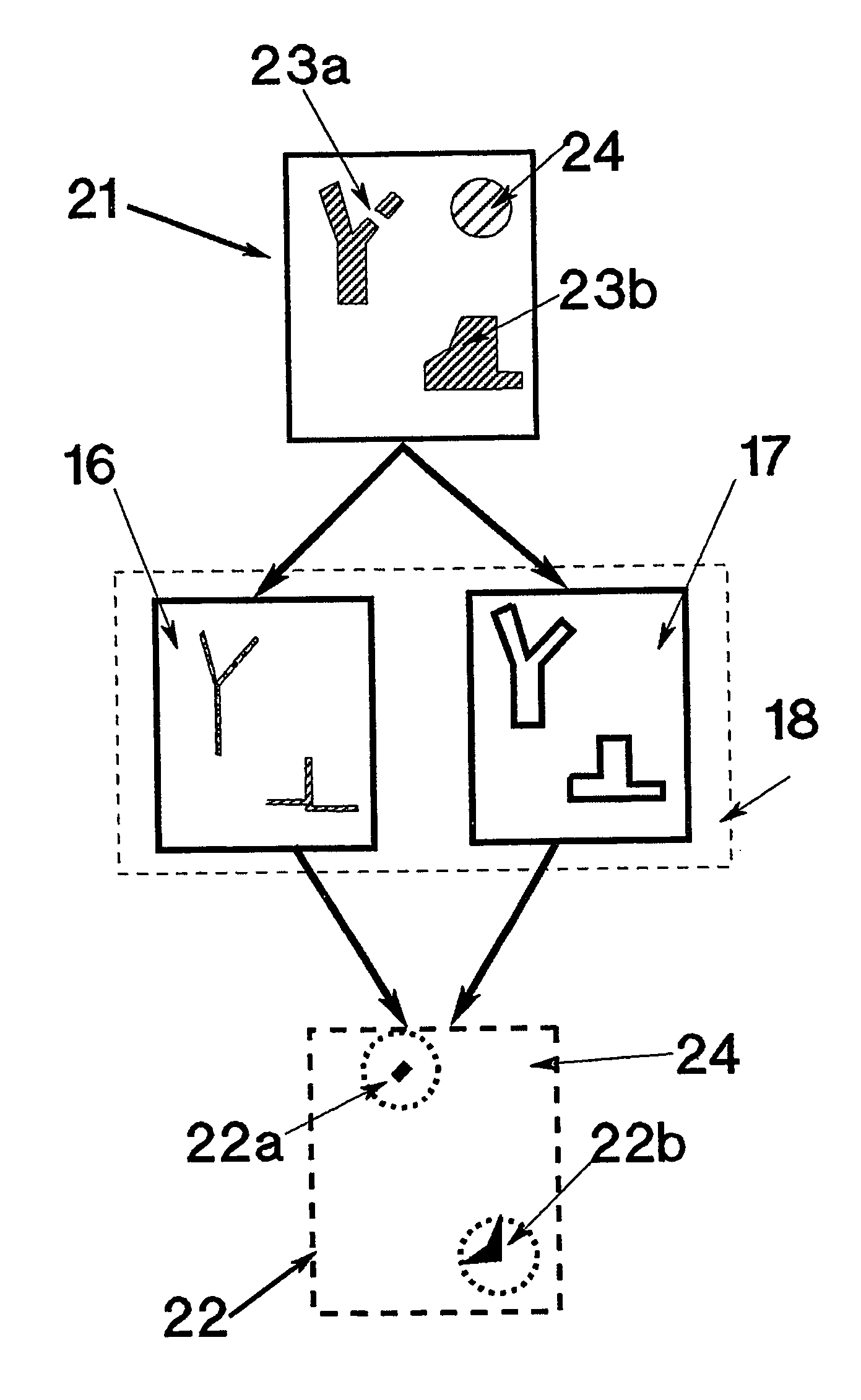
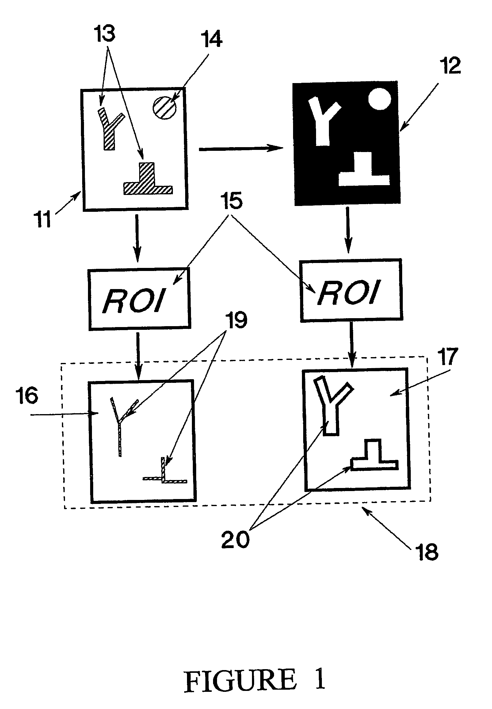
[0019]The present invention is a morphological inspection method based on a comparison of real images.

[0020]According to the method of the present invention, defining regions of interest on a first-color image of the inspection reference object. The non-defined regions are ignorable. Then, skeletonizing the image having a first-color image. In the next step, inversing the inspection reference object image and changing its color. Defining regions of interest and skeletonizing the image, having a second-color image of the objects edges. The first-color image contains skeletons of the interest objects, while the second-color image contains edges of the interest objects.

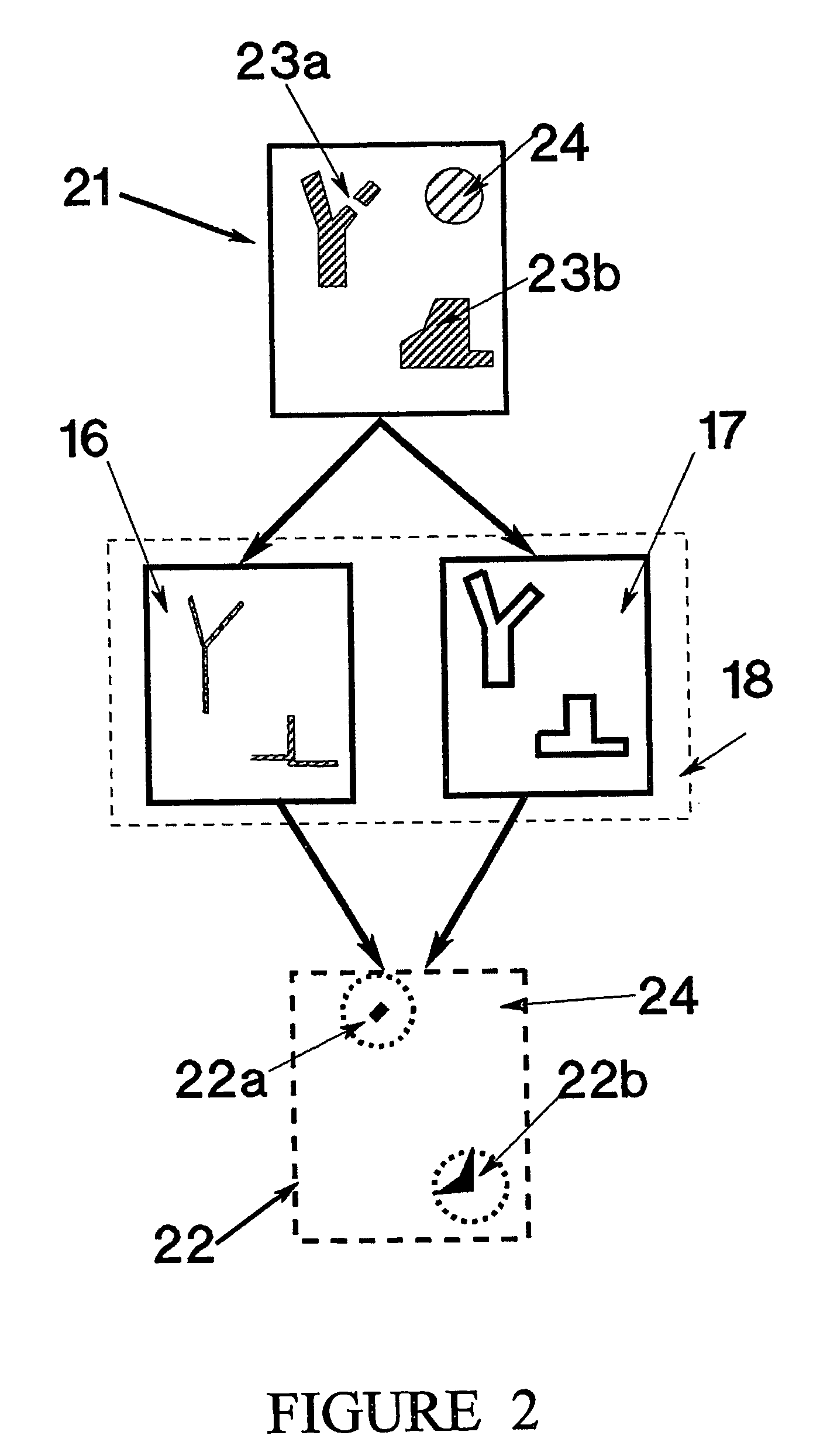
[0021]In the inspection process, comparing a third-color image of the inspected object, with the first-color image. This comparison marks the defects of objects' shape. Then, comparing the third-color image of the inspected object, with the second-color image. This comparison marks the defects of objects' edges. By addin...


PUM

PropertyMeasurementUnit
coloraaaaaaaaaa
defect scannersaaaaaaaaaa
optical inspectionaaaaaaaaaa

Abstract

A morphological inspection method based on a comparison of real images—a real reference image and a real inspected image of an inspected object is disclosed.

Description

FIELD OF THE INVENTION[0001]The present invention relates to a morphological tracking method. More specifically, the present invention relates to an inspection method that is useful in automatic inspection.BACKGROUND OF THE INVENTION[0002]Defects in the form of structural flaws, process residues, and external contamination occur during the production of objects such as Printed Circuit Boards, semiconductor wafers, artwork or reticles. Defects are typically detected by a class of instruments called defect scanners (or automatic optical inspection systems). Such instruments automatically scan the object's surfaces and detect morphological or design anomalies using a variety of techniques. The location of these anomalies with respect to the patterns on the object's surface is recorded. This information, or “defect map,” is stored in a computer file and sent to a defect review station.[0003]Using the defect map to locate each defect, a human operator observes each defect under a microsc...

Claims


Application Information

Patent Timeline
Patent Type & Authority Patents(United States)
IPC IPC(8): G06K9/00G01B11/24G01N21/956G06T1/00G06T5/00G06T5/30G06T7/00H01L21/66
CPCG06T7/001G06T7/0083G06T7/60G06T7/0091G06T2207/30148G06T2207/20044G06T7/12G06T7/155
Inventor FLIESWASSER, RONIYANUKA, MOTIDOLGIN, BORIS
Owner CAMTEK LTD
Why Eureka
Try Eureka