Two-shaft turbocharger

a turbocharger and two-shaft technology, applied in combination engines, machines/engines, mechanical apparatus, etc., can solve the problems of increasing the overall cost of an internal combustion engine by a significant amount, affecting the overall performance of the engine, so as to reduce the incidence, improve the transient response time, and limit the volume

Inactive Publication Date: 2009-08-11
HONEYWELL INT INC
View PDF27 Cites 38 Cited by
  • Summary
  • Abstract
  • Description
  • Claims
  • Application Information

AI Technical Summary

Benefits of technology

[0008]In various embodiments, the present invention solves some or all of the needs mentioned above, typically providing a two-shaft turbocharger system that provide an increased pressure ratio and an extended flow range, while minimizing cost, size, weight and response time. Preferably these apparatus operate to accurately control EGR flow rate over a broad range of engine and compressor operating points, and minimize engine back-pressure to reduce engine pumping losses.
[0010]Advantageously, the first axial compressor directing air into the axial duct provides for a responsive, low-pressure compressor providing pressurized air into a second compressor, wherein the duct has a limited volume so as to improve transient response time. Additionally, the axial compressor can be used at low boost levels to generate swirl entering the second compressor, which can minimize incidence on the second compressor wheel's blades, so as to provide a greater low-flow (surge) flow range than might be possible with a single stage compressor, thereby increasing the flow range on the low-flow side of the turbocharger's compressor map. This greater flow range can be accomplished without the pressure loss, and related inefficiency loss, which would occur due to the use of inlet guide vanes. Furthermore, because the axial compressor will increase the density of the air entering the second compressor, the high-flow (choke) flow rate will increase, thereby increasing the flow range on the high-flow side of the turbocharger's compressor map.
[0011]The invention typically further features that the housing defines a second axial duct that extends between the first and second turbine wheels, and that the second turbine wheel is a radial turbine wheel configured to direct airflow axially through the second axial duct toward the first turbine wheel. Advantageously, the second radial turbine directing air into the second axial duct provides for a responsive, low-pressure turbine to receive pressurized exhaust from the radial turbine, wherein the duct has a limited volume to improve transient response time.
[0012]The invention further features the use of vanes within the first and second axial ducts. The vanes preferably have a controllable geometry, and there is a control system providing for accurate and individual control over the speed of each turbine, and providing for improved surge and choke characteristics.

Problems solved by technology

An arrangement of in-series turbochargers may add significant size, weight and cost to the overall cost of an internal combustion engine.
Additionally, in-series turbochargers must be interconnected by interstage ducting, which can slow overall response time.
A challenge in designing an LST turbine is that it must provide the required power to efficiently drive both compressors, while having a sufficiently low rotational inertia so as to operate comparably with series turbochargers in terms of transient response.

Method used


Image

  • Two-shaft turbocharger
  • Two-shaft turbocharger
  • Two-shaft turbocharger

Examples


Embodiment Construction

[0020]The invention summarized above and defined by the enumerated claims may be better understood by referring to the following detailed description, which should be read with the accompanying drawings. This detailed description of particular preferred embodiments of the invention, set out below to enable one to build and use particular implementations of the invention, is not intended to limit the enumerated claims, but rather, it is intended to provide particular examples of them.

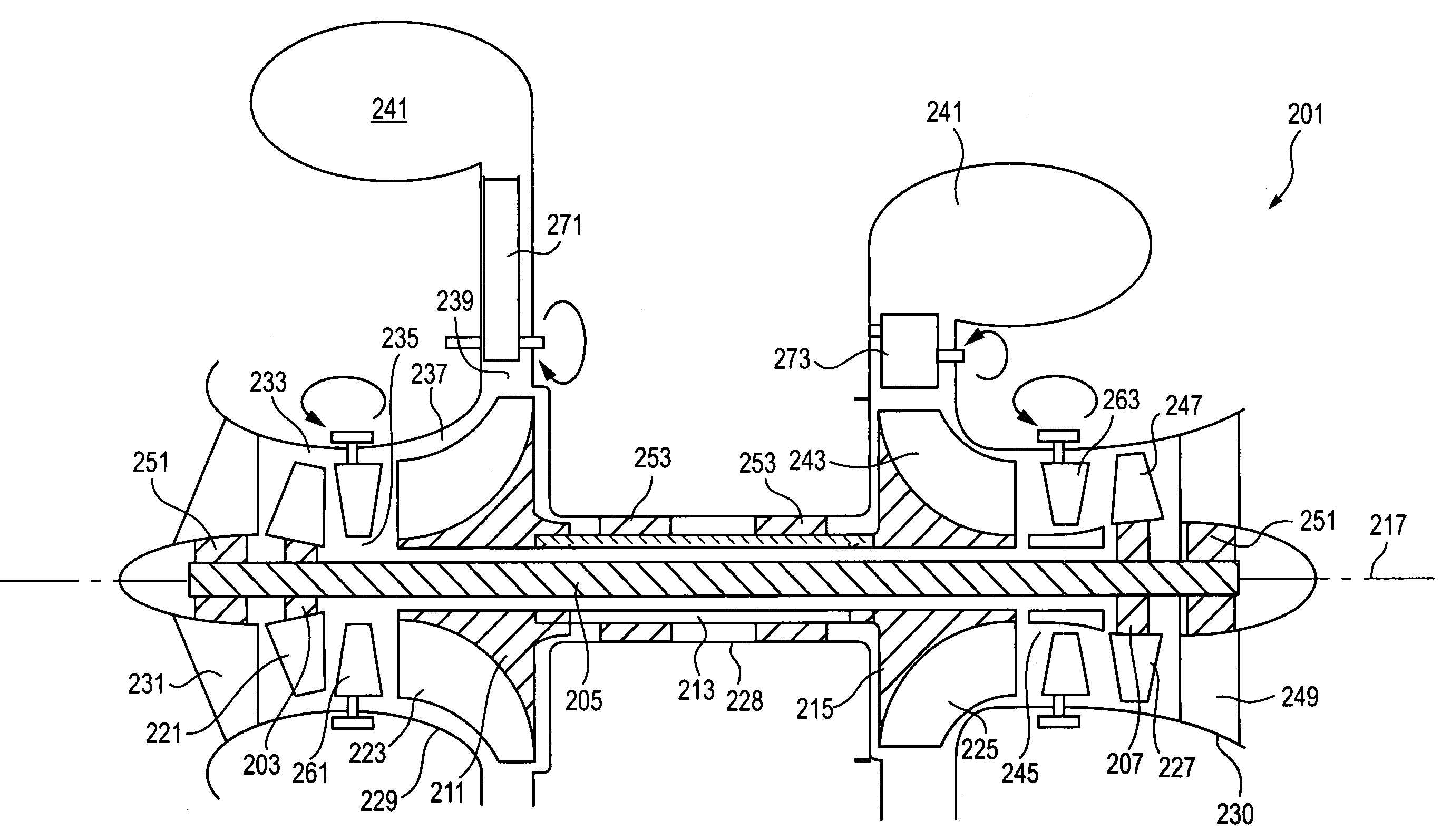
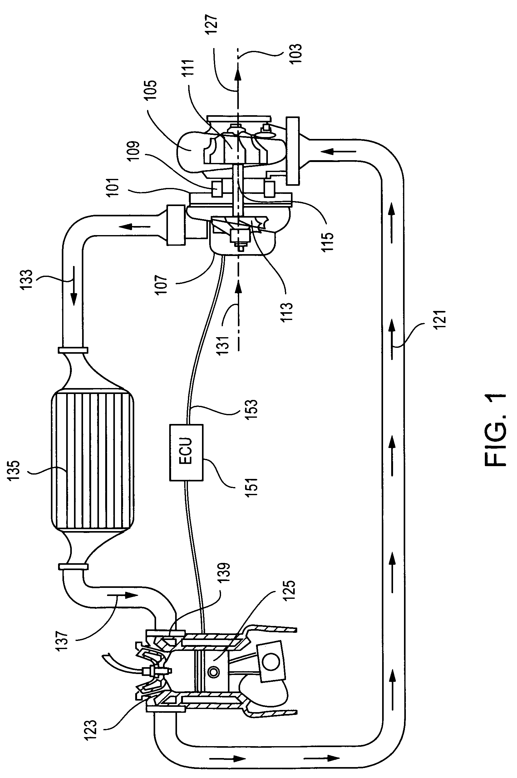
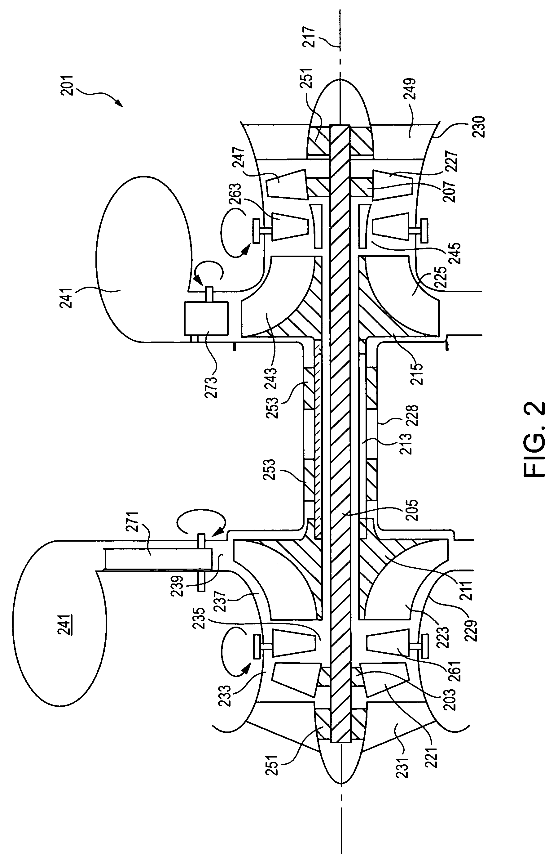
[0021]Typical embodiments of the present invention reside in a dual shaft axial-radial turbocharger, along with associated methods and apparatus. With reference to FIG. 2, a turbocharger 201 under the present invention is usable with an internal combustion engine in a fashion similar to a typical turbocharger, as described with reference to FIG. 1. The turbocharger includes a first, inner rotor, including a first-stage, low-pressure, axial compressor wheel 203, an inner shaft 205, and a second-stage, low...


PUM


Abstract

A turbocharger, having an axial compressor wheel and an axial turbine wheel mounted on a first shaft supported by a housing, and a radial compressor wheel and a radial turbine wheel mounted on a second shaft, the second shaft concentrically extending around the first shaft and being supported by the housing. The housing defines a first duct extending axially from the exducer of the axial compressor to the inducer of the radial compressor, and a second duct extending axially from the exducer of the radial turbine to the inducer of the axial turbine. A plurality of controllable compressor guide vanes extend through the first duct, and a plurality of controllable turbine stator vanes extend through the second duct. The housing is provided with variable diffuser vanes at the exducer of the radial compressor, and with variable turbine vanes at the inducer of the radial turbine. The variable turbine vanes and the turbine stator vanes are controlled to accurately control the rotation rate of the radial and axial turbines. The compressor guide vanes are controlled to minimize surge and maximize choke flow rate.

Description

[0001]The present invention relates generally to compressors for turbomachinery and, more particularly, to apparatus and methods of operating a two-shaft turbocharger.BACKGROUND OF THE INVENTION[0002]Turbochargers are used in a variety of applications for providing compressed gas for the operation of an internal combustion engine. As an example, with reference to FIG. 1, a turbocharger 101 includes a turbocharger housing and a rotor configured to rotate within the turbocharger housing along an axis of rotor rotation 103 on thrust bearings and journal bearings. The turbocharger housing includes a turbine housing 105, a compressor housing 107, and a bearing housing 109 that connects the turbine housing to the compressor housing. The rotor includes a turbine wheel 111 located substantially within the turbine housing, a compressor wheel 113 located substantially within the compressor housing, and a shaft 115 extending along the axis of rotor rotation, through the bearing housing, to con...

Claims


Application Information

Patent Timeline
Patent Type & Authority Patents(United States)
IPC IPC(8): F02B33/44
CPCF01D17/162F01D17/165F02B37/013F02B37/24F02C3/085F04D17/025F04D25/04F02B37/004F02C6/12F05D2270/10Y02T10/144Y02T10/12
Inventor VRBAS, GARY D.
Owner HONEYWELL INT INC
Why Eureka
Try Eureka