Connector

a technology of connecting parts and connectors, applied in the direction of incorrect coupling prevention, coupling device connection, electrical equipment, etc., can solve problems such as electrical connection defects, and achieve the effect of reducing contact portion wear

Active Publication Date: 2009-08-11
YAZAKI CORP
View PDF5 Cites 12 Cited by
  • Summary
  • Abstract
  • Description
  • Claims
  • Application Information

AI Technical Summary

Benefits of technology

[0009]This invention has been made in view of the above problems, and an object of the invention is to provide a connector in which a load, applied to female and male terminals, can be reduced, and also relative motion of mutually-fitted female and male connector housings both in a fitting direction and in a direction perpendicular to the fitting direction can be suppressed, thereby reducing wear of contact portions of the female and male terminals.
[0023]When the inner housing is not fitted into the female connector housing, the inner housing contacts the outer housing in the second direction perpendicular to the first direction, or is disposed in such a manner that the second gap is formed between the inner housing and the outer housing in the second direction perpendicular to the first direction. Therefore, during the operation for fitting the inner housing into the female connector housing, relative motion of the inner housing in the second direction is suppressed, and the inner housing can be smoothly fitted into the female connector housing.
[0024]When the inner housing is fitted in the female connector housing, the inner housing is disposed in such a manner that the first gap, being greater than the second gap, is formed between the inner housing and the outer housing in the second direction. Therefore, even when vibration acts on the connector, so that relative motion of the female and male connector housings occurs, the outer housing is prevented from interfering with the inner housing, and the load of the outer housing will not act on the female and male terminals. Therefore, the load, acting on the female and male terminals, is reduced, so that the load, acting on contact portions of these terminals, can be reduced.
[0025]In the connector of the construction of the above Paragraph (2), during the operation for fitting the inner housing into the female connector housing, the inner housing is moved in the first direction, and by doing so, the rib of the inner housing is displaced in the fitting direction, and is completely brought out of registry with the corresponding rib reception portion of the outer housing. As a result, a gap, corresponding to a height of the rib reception portion, is formed between the rib and the inner surface of the outer housing, and also a gap, corresponding to a height of the rib, is formed between the rib reception portion and the outer surface of the inner housing. With this simple construction, when the inner housing is not fitted in the female connector housing, the inner housing contacts the outer housing in the second direction, or is disposed in such a manner that the second gap is formed between the inner housing and the outer housing in the direction perpendicular to the fitting direction. Also, when the inner housing is fitted in the female connector housing, the inner housing is disposed in such a manner that the first gap, larger than the second gap, is formed between the inner housing and the outer housing in the second direction perpendicular to the first direction.
[0026]In the connector of the construction of the above Paragraph (3), the first slanting surface is formed on the outer surface of the inner housing, and the second slanting surface is formed on the inner surface of the female connector housing, and the first slanting surface is mated with the second slanting surface. These slanting surfaces intersect the first direction, and therefore relative motion of the inner housing and the female connector housing (which are fitted together) both in the fitting direction and in the second direction perpendicular to the fitting direction can be suppressed. Furthermore, when the mating slanting surfaces are worn, the inner housing is inserted deeper into the female connector housing, so that the first slanting surface is kept mated respectively with the second slanting surface, and therefore the relative motion can be suppressed for a long period of time.
[0028]In the connector of the present invention, a load, applied to the female and male terminals, can be reduced, and also relative motion of the mutually-fitted female and male connector housings both in the first direction and in the second direction perpendicular to the first direction can be suppressed, thereby reducing wear of the contact portions of the female and male terminals.

Problems solved by technology

A connector, used, for example, in the wiring of a vehicle such as an automobile, undergoes vibration developing during the travel of the vehicle, and contact portions of female and male terminals are worn by such vibration, and in some cases the electrical connection becomes defective.

Method used


Image

  • Connector
  • Connector
  • Connector

Examples


Embodiment Construction

[0035]One preferred embodiment of a connector of the present invention will now be described in detail with reference to the drawings.

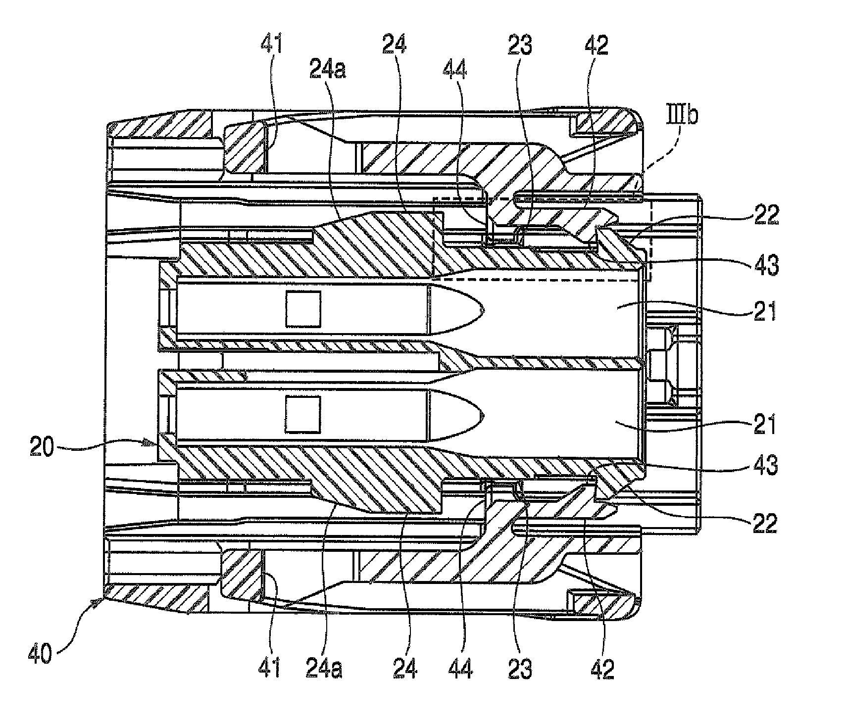
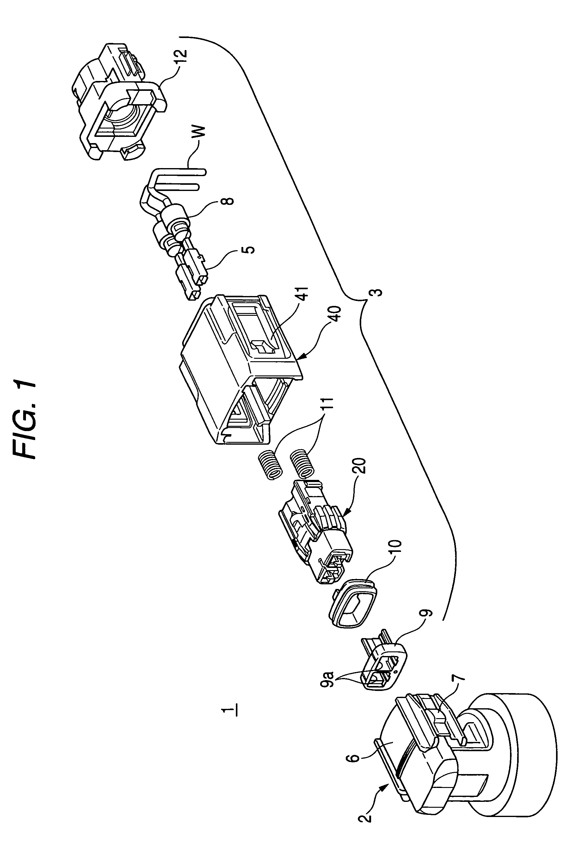
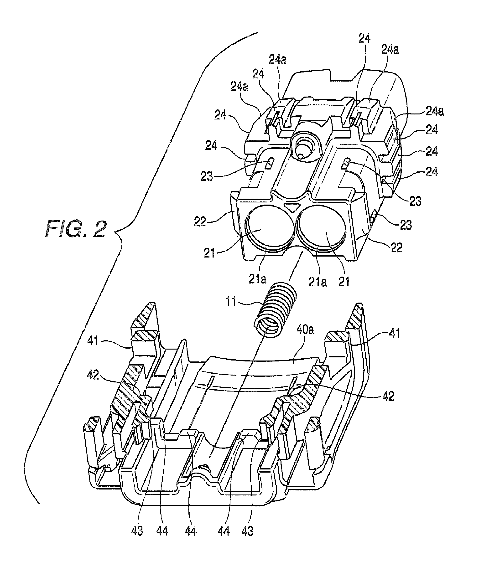
[0036]FIG. 1 is an exploded, perspective view of the connector of this embodiment, FIG. 2 is a perspective view showing an inner housing and an outer housing of a male connector housing, with the outer housing shown as been partly broken, FIG. 3A is a cross-sectional view of the male connector housing which is not fitted in a female connector housing, FIG. 3B is an enlarged view of a portion surrounded by a broken line IIIb of FIG. 3A, FIG. 4A is a cross-sectional view of the male connector housing fitted in the female connector housing, and FIG. 4B is an enlarged view of a portion surrounded by a broken line IVb of FIG. 4A.

[0037]As shown in FIG. 1, the connector 1 of this embodiment includes the female connector housing 2 which holds male terminals 4 (indicated by dot-and-dash lines in FIG. 4A), and the male connector housing 3 receiving female termi...


PUM


Abstract

A connector includes a female connector housing, that has a male terminal, and a male connector housing that has a female terminal for electrical connecting to the male terminal, and that is adapted to be fitted into the female connector. The male connector housing includes an inner housing which has the female terminal, and which is adapted to be fitted in the female connector housing so that the female terminal is connected to the male terminal, and an outer housing which is adapted to support the inner housing so that the inner housing is movable in a first direction in which the inner housing is fitted in the female connector housing and in a second direction perpendicular to the first direction. When the inner housing is fitted into the female connector housing, the inner housing is disposed so as to separate from the outer housing in the second direction with a first gap.

Description

BACKGROUND OF THE INVENTION[0001]This invention relates to a connector for electrically connecting female and male terminals together, and more particularly to a connector in which wear of contact portions of the female and male terminals due to vibration is reduced.[0002]A connector, used, for example, in the wiring of a vehicle such as an automobile, undergoes vibration developing during the travel of the vehicle, and contact portions of female and male terminals are worn by such vibration, and in some cases the electrical connection becomes defective. Therefore, there is known a conventional connector in which relative motion between female and male connector housings, fitted together, is suppressed so as to reduce wear of contact portions of female and male terminals which rub against each other (see, for example, JP-A-2002-198127 (Pages 3 to 4, FIGS. 4 and 6)).[0003]As shown in FIGS. 5A and 5B, the connector 100, disclosed in JP-A-2002-198127, comprises the female connector hou...

Claims


Application Information

Patent Timeline
Patent Type & Authority Patents(United States)
IPC IPC(8): H01R13/64
CPCH01R13/6315
Inventor KOZONO, SEIJIMATSUNAGA, TAKASHIKOBAYASHIMINAKATA, MASATONISHIDA, ATSUSHI
Owner YAZAKI CORP
Why Eureka
Try Eureka