Ventilation system

a technology of ventilation system and air flow resistance, which is applied in ventilation system, lighting and heating apparatus, heating types, etc., can solve the problems of system not being able to achieve an object, inability to properly maintain humidity of indoor space, and inability to achieve objects. to achieve the effect of reducing air flow resistan

Inactive Publication Date: 2009-08-11
LG ELECTRONICS INC
View PDF25 Cites 48 Cited by
  • Summary
  • Abstract
  • Description
  • Claims
  • Application Information

AI Technical Summary

Benefits of technology

[0013]An object of the present invention is to provide a ventilation system having a module that can control the indoor humidity.
[0014]Another object of the present invention is to provide a ventilation system that can be operated under a variety of operation conditions by reducing the air flow resistance even though there is some reduction in the ventilation performance.
[0015]Still another object of the present invention is to provide a ventilation system in which components are formed in module types so that the selective installation thereof can be easily performed.
[0017]To achieve these objects and other advantages and in accordance with the purpose of the invention, as embodied and broadly described herein, there is provided a ventilation system including: a ventilation module having a heat exchanger module; an IAQ (indoor air quality) module for improving quality of air passing through the ventilation module; and a case for guiding the air that consecutively passes through the ventilation module and the IAQ module.
[0019]In still another aspect of the present invention, there is provided a ventilation system including: a ventilation module receiving at least a heat exchanger module; and an IAQ module receiving a dehumidifier module and a filter module for improving quality of air passing through the ventilation module, wherein the dehumidifier module or the filter module are independently mounted or dismounted.
[0021]Since the components are formed in module types, the selective installation thereof can be easily performed and thus the product application of the ventilation system can be more convenient.

Problems solved by technology

However, there is a limitation in improving the indoor environment.
That is, the ventilation system can achieve an object that cannot be achieved by a general air conditioner that can control only the temperature and humidity.
First, the indoor temperature can be constantly maintained by using a heat exchanger. However, the humidity of the indoor space cannot be properly maintained. Therefore, an additional humidifier or dehumidifier is required. That is, the conventional ventilation system simply performs the ventilation function but cannot actively improve the indoor air quality.
Furthermore, since the air flow passage is complicated, the airflow resistance and the noise caused by he airflow resistance increase.

Method used


Image

  • Ventilation system
  • Ventilation system
  • Ventilation system

Examples


first embodiment

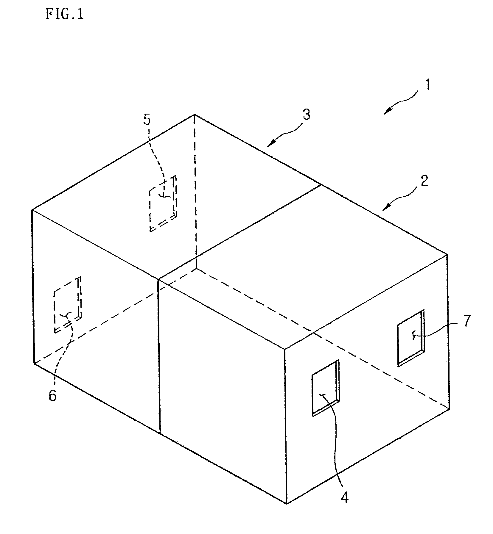
[0036]FIG. 1 is a perspective view of a ventilation system according to an embodiment of the present invention.

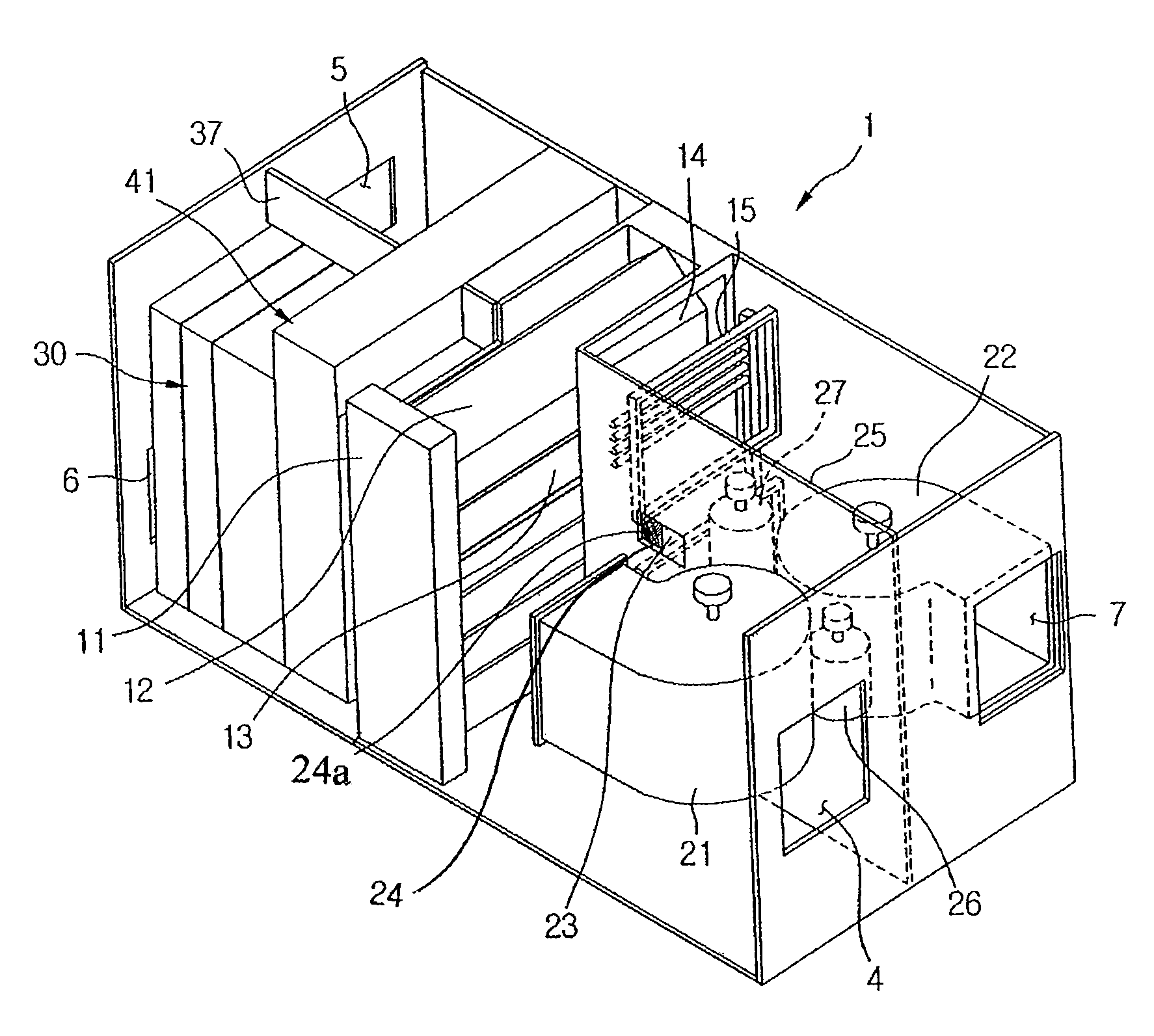
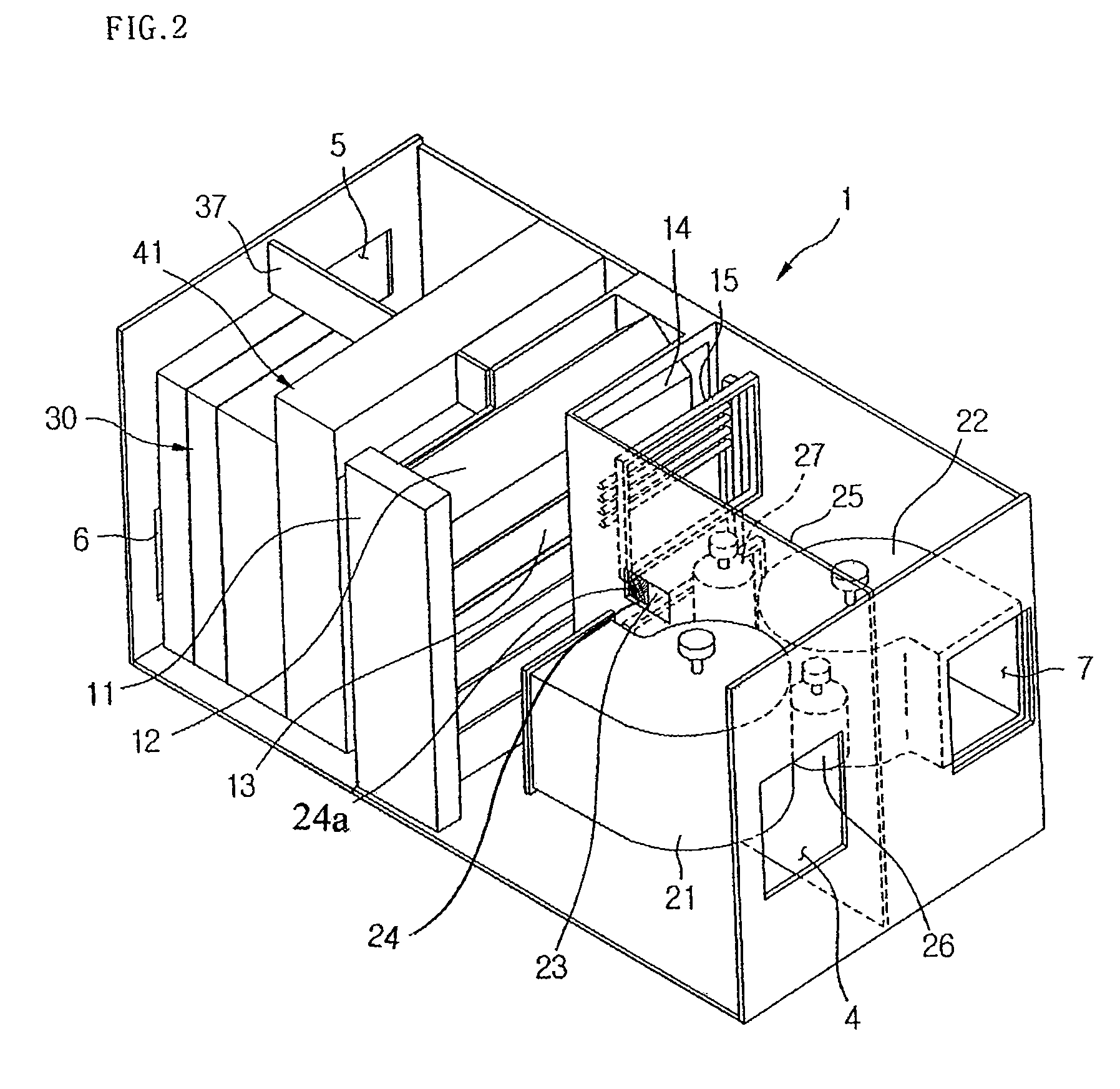
[0037]Referring to FIG. 1, a ventilation system 1 includes a case, a ventilation module 2 protected by the case and disposed at a side of the ventilation system, and an IAQ module 3 disposed at another side of the ventilation module.

[0038]As the ventilation module 2 and the IAQ module 3 are horizontally arranged in parallel, the user can conveniently replace each component of the IAQ module 3 and efficiently use the indoor space.

[0039]Meanwhile, a fan and an electric heat exchanger are provided in the ventilation module 2 to forcedly circulate the indoor air. The circulating air is heat-exchanged by the electric heat exchanger to maintain a temperature of the indoor air.

[0040]In addition, a humidifier or a dehumidifier may be disposed in the IAQ module 3 to control the humidity of the indoor air.

[0041]In addition, the ventilation system 1 is provided with an air inlet / outle...

second embodiment

[0074]A second embodiment of the present invention is identical to the first embodiment except that a structure and mounting location of the ventilation module 101 is different. Therefore, the description of the like parts will quote the first embodiment.

[0075]FIG. 10 is a perspective view illustrating an outer appearance of a ventilation system according to a second embodiment of the present invention.

[0076]Referring to FIG. 10, a ventilation system 100 of this embodiment includes a ventilation module 101 and an IAQ module 102. An air exhaust inlet 104 and an air supply outlet 103 are formed in front of the ventilation module 101. An air supply inlet 105 and an air exhaust outlet 106 are formed in rear of the IAQ module 102.

[0077]An air supply fan 152 and an air exhaust fan 151 are disposed in the ventilation module 101. In addition, an electric heat exchanger module 110 is disposed in rear of the fans 151 and 152. A humidifier module 120 is disposed at a portion through which the ...


PUM


Abstract

A ventilation system includes a ventilation module having a heat exchanger module, an IAQ module for improving quality of air passing through the ventilation module, and a case for guiding the air that consecutively passes through the ventilation module and the IAQ module.

Description

BACKGROUND OF THE INVENTION[0001]1. Field of the Invention[0002]The present invention relates to a ventilation system, and particularly, to a ventilation system that can perform massive ventilation. More particularly, the present invention relates to a ventilation system, in which each function for performing an air conditioning function is formed in a module type so that the installing convenience and comfortableness can be improved.[0003]2. Description of the Related Art[0004]Recently, the people have had a great interest in health. Particularly, there is a significant desire for a comfortable indoor environment where people are living. The comfortableness of the indoor environment is generally realized by the air condition process. However, there is a limitation in improving the indoor environment. Therefore, a ventilation system that can introduce fresh external air and exhaust indoor air has been spotlighted. The ventilation system is a system that can freshly maintain an indoo...

Claims


Application Information

Patent Timeline
Patent Type & Authority Patents(United States)
IPC IPC(8): F24F12/00F24F13/20F24F3/14
CPCF24F3/1411F24F3/1423F24F13/20F24F6/14F24F2203/1084F24F2203/1012F24F2203/1032F24F2203/1056F24F2203/1068F24F2003/144F24F11/0001
Inventor CHOI, DONG HWANKIM, KYUNG HWANYIM, NAM SIKCHOI, HO SEONCHOI, KEUN HYOUNG
Owner LG ELECTRONICS INC
Why Eureka
Try Eureka