High pressure applicator

a technology of applicators and cylinders, applied in the field of instruments, can solve the problems of limited viscosity of pmma, insufficient volume to complete the procedure, and complicated procedures, and achieve the effect of high pressur

Inactive Publication Date: 2009-08-11
NEUROTHERM
View PDF252 Cites 100 Cited by
  • Summary
  • Abstract
  • Description
  • Claims
  • Application Information

AI Technical Summary

Benefits of technology

[0013]At least one sealing element may be provided to interface with the inner wall of the first column, to enhance the generation of pressure in the first column. A handle is also preferably integrally formed with or affixed to the second column and may extend radially therefrom to provide a user a mechanical advantage upon grasping it.
[0016]In another embodiment, a plunger element is provided which is adapted to be inserted within the first and second columns. The plunger element has a first end portion and a second end portion, where the first end portion is adapted and configured to closely fit within the inner wall of the first column to form a pressure seal therewith. At least one sealing element may be provided for the first end portion to form and / or enhance a pressure seal between the inner wall and the plunger element A handle may be integrally formed with or affixed to the second column, to optionally extend radially therefrom, to provide the user a mechanical advantage upon grasping it. The plunger element may further be provided with at least one frictional element mounted to the second end portion and adapted to form a disengageable friction fit with the second column at or near the closed end of the second column.
[0020]In yet another embodiment, the first column is substantially hollow and comprises an inside wall, an open first end and a closed second end, and a barrel portion of a syringe is received therein. A plunger portion of the syringe is received within a second column. The applicator may include threading on an outer wall of the first column and threading on an inner wall of the second column, where the threads are engageable with one another to provide a driving force for driving the plunger portion with respect to the barrel portion. A handle may be integrally formed with or affixed to the second column and optionally extend radially therefrom and to provide the user a mechanical advantage upon grasping it.

Problems solved by technology

Because in general, 10 cc syringes are only capable of generating pressures of about 100-150 psi, this places a limitation on the viscosity of the PMMA that can be effectively “pushed through” the syringe and cannula and fully delivered to the implant site.
A serious limitation with the use of a 1 cc syringe, however, is that it will not hold a large enough volume to complete the procedure in one step or “load” and must be reloaded several times to complete the procedure, since, on average, about 3.5 cc of implant material per side of the vertebral body are required for an implantation procedure.
This makes the procedure more complicated with more steps, and more risky in that the polymerization of the implant material causes it to become increasingly more viscous during the additional time required for reloading.
Another problem with a 1 cc syringe is lack of control, as high pressures are, generated in a “spike-like” response time and are not continuously controllable.
Leakage or seepage of PMMA from the vertebral implant site can cause a host of complications some of which can be very serious and even result in death.
A leak toward the distal veins poses an even more serious risk, since this can cause a pulmonary embolism which is often fatal.
Since there is a limited amount of time to work with PMMA before it begins to polymerize or set up, this type of procedure is more difficult to successfully complete within the allotted time, and thus poses an additional risk to the success of the operation.

Method used


Image

  • High pressure applicator
  • High pressure applicator
  • High pressure applicator

Examples


Embodiment Construction

[0056]The present invention substantially improves the delivery of hard tissue implant sites to the targeted zone of implantation, and is especially well suited for percutaneous deliveries. The present invention substantially reduces several of the risk factors associated with the performance of percutaneous vertebroplasty. Additionally, the present invention enables an increase in an upper acceptable viscosity value of the implant to be delivered because of the increase in the amount of pressure available for controllably driving the delivery.

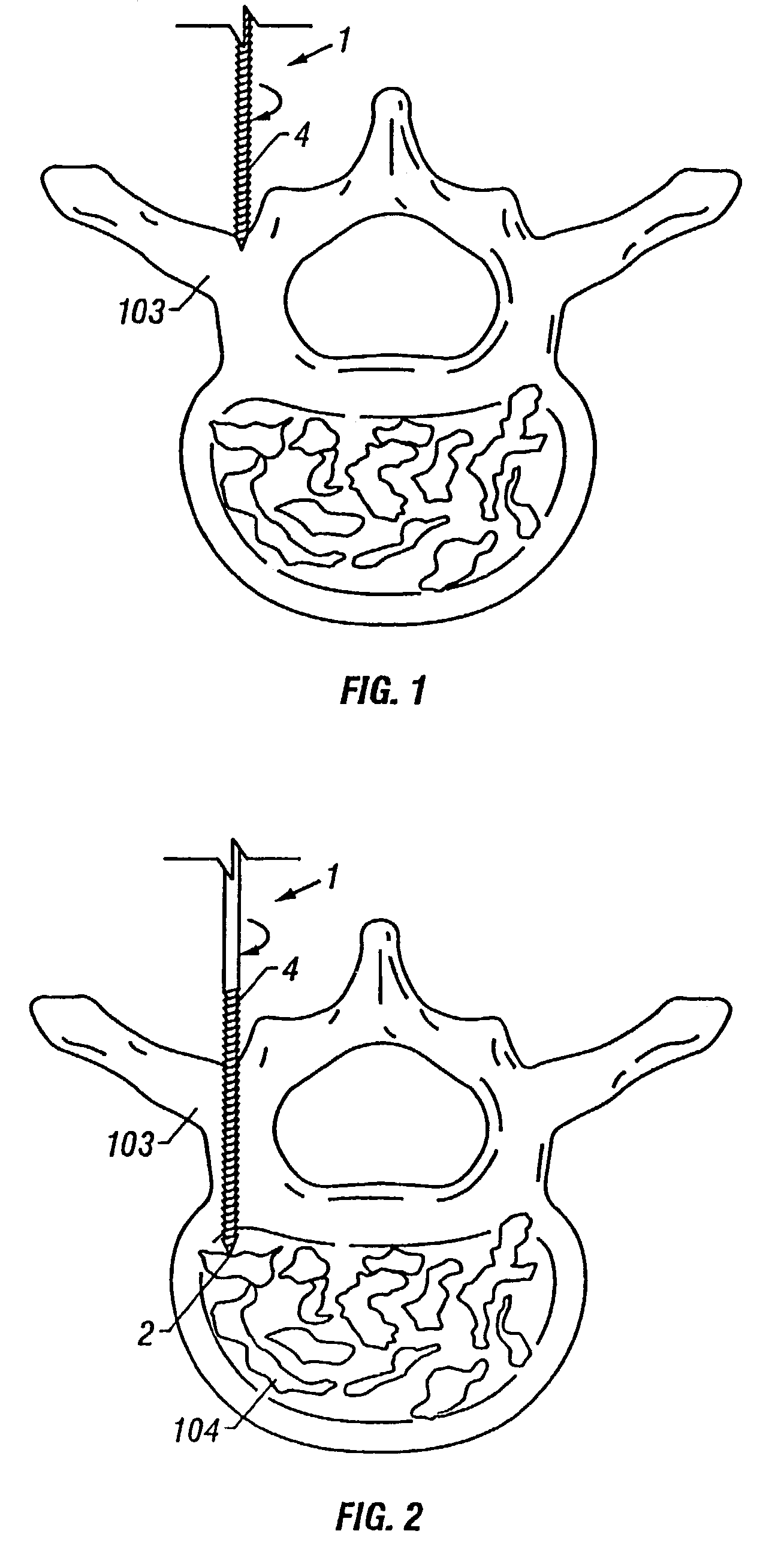
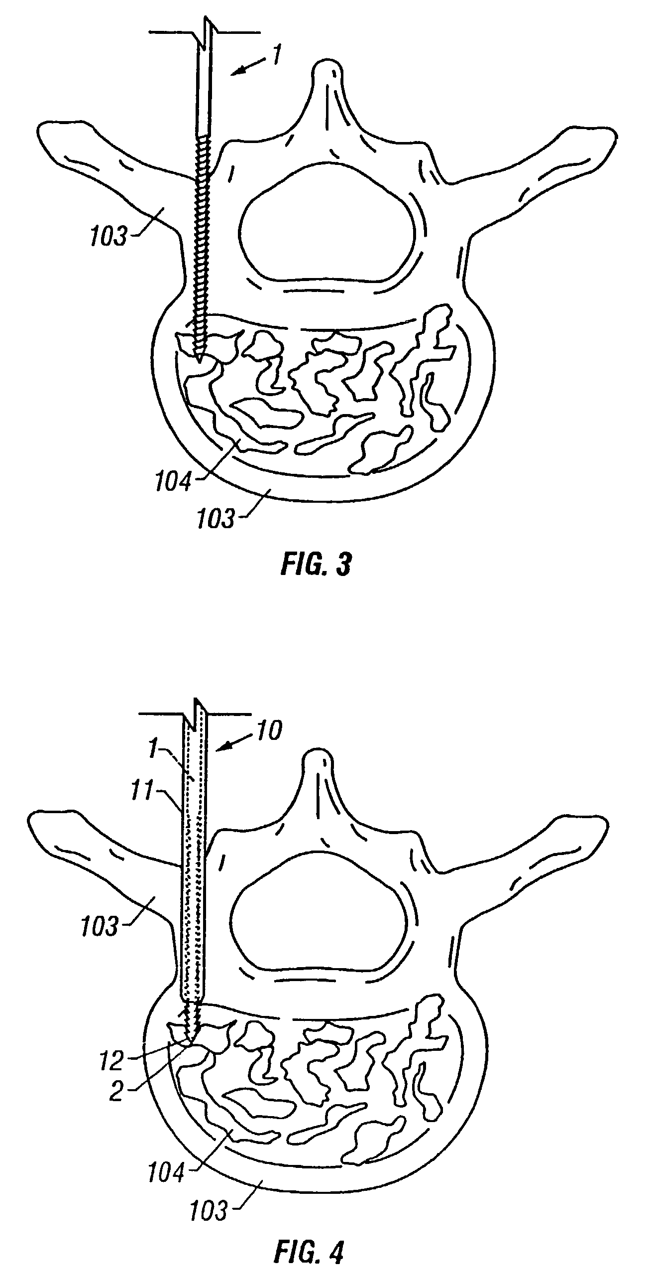
[0057]An example of a procedure for performing percutaneous vertebroplasty is illustrated in FIGS. 1-6. Beginning with FIG. 1, an example of the use of depth guided instruments will now be described. For a more detailed description of various depth-guided instruments that can be used for accessing the cortical bone, the reader is directed to copending application Ser. No. 08 / 950,382, filed on Oct. 14, 1997, entitled “Precision Depth Guided Ins...


PUM


Abstract

A pressure applicator for applying pressure to a flowable implant material, e.g., PMMA. A pressure applicator or driver includes a pair of columns which are engageable with one another, preferably by threads to generate a driving pressure. A handle is provided for the operator to grasp and steady the device as he turns the handle to apply pressure to the implantable material within the applicator. A luer-lock or other connecting device is provided for attaching the applicator to a cannula (or a connecting conduit that in turns connects with a cannula) that will deliver the implant material to the desired site. Pressures of about 1000-3000 psi may be generated by this device.

Description

CROSS REFERENCE TO RELATED APPLICATIONS[0001]This application is a continuation of application Ser. No. 10 / 039,892, filed Oct. 26, 2001, now abandoned, which is a divisional of Application Ser. No. 09 / 409,934, filed Sep. 30, 1999, now U.S Pat. No. 6,383,190, which is a continuation in part of application Ser. No. 09 / 053,108, filed Apr. 1, 1998, now abandoned, entitled “Pressure Applicator for Hard Tissue.”TECHNICAL FIELD[0002]The present invention relates to instruments for more accurately controlling the placement of implant material thereof, during surgical procedures for the repair of hard tissue by injection of hard tissue implant materials. Procedures for such repair include hip augmentation, mandible augmentation, and particularly vertebroplasty, among others.BACKGROUND ART[0003]Polymethylmethacrylate (PMMA) has been used in anterior and posterior stabilization of the spine for metastatic disease, as described by Sundaresan et al., “Treatment of neoplastic epidural cord compre...

Claims


Application Information

Patent Timeline
Patent Type & Authority Patents(United States)
IPC IPC(8): A61B17/58A61B17/88A61F2/44A61F2/46
CPCA61B17/8819A61B17/8822A61F2/4601A61B17/8833A61B17/8816A61F2002/4677A61F2/44A61F2002/4623A61F2/4603
Inventor PREISSMAN, HOWARD E.
Owner NEUROTHERM
Why Eureka
Try Eureka