Electronic device with airflow guiding duct

a technology of airflow and guiding ducts, applied in the direction of power cables, cables, insulated conductors, etc., can solve the problem of adding to the cost of labor in manufacturing

Inactive Publication Date: 2009-08-11
HON HAI PRECISION IND CO LTD
View PDF14 Cites 24 Cited by
  • Summary
  • Abstract
  • Description
  • Claims
  • Application Information

AI Technical Summary

Benefits of technology

[0004]A heat dissipating module is generally mounted on a motherboard of an electronic device, such as a computer or a server, for dissipating heat generated by electronic components in the electronic device. With the development of the computer industry, heat generated by the electronic components becomes greater due to faster speeds of the computers or servers. The conventional heat dissipating module cannot satisfy the requirements of current computer or server systems by itself so an airflow guiding duct is usually mounted above the heat dissipating module on the motherboard, for guiding airflow, increasing effectiveness heat dissipation. Conventionally, the airflow guiding duct is mounted in the electronic device via screws or bolts. This method involves many fasteners and adds to cost of labor in manufacturing.

Problems solved by technology

This method involves many fasteners and adds to cost of labor in manufacturing.

Method used


Image

  • Electronic device with airflow guiding duct
  • Electronic device with airflow guiding duct
  • Electronic device with airflow guiding duct

Examples


Embodiment Construction

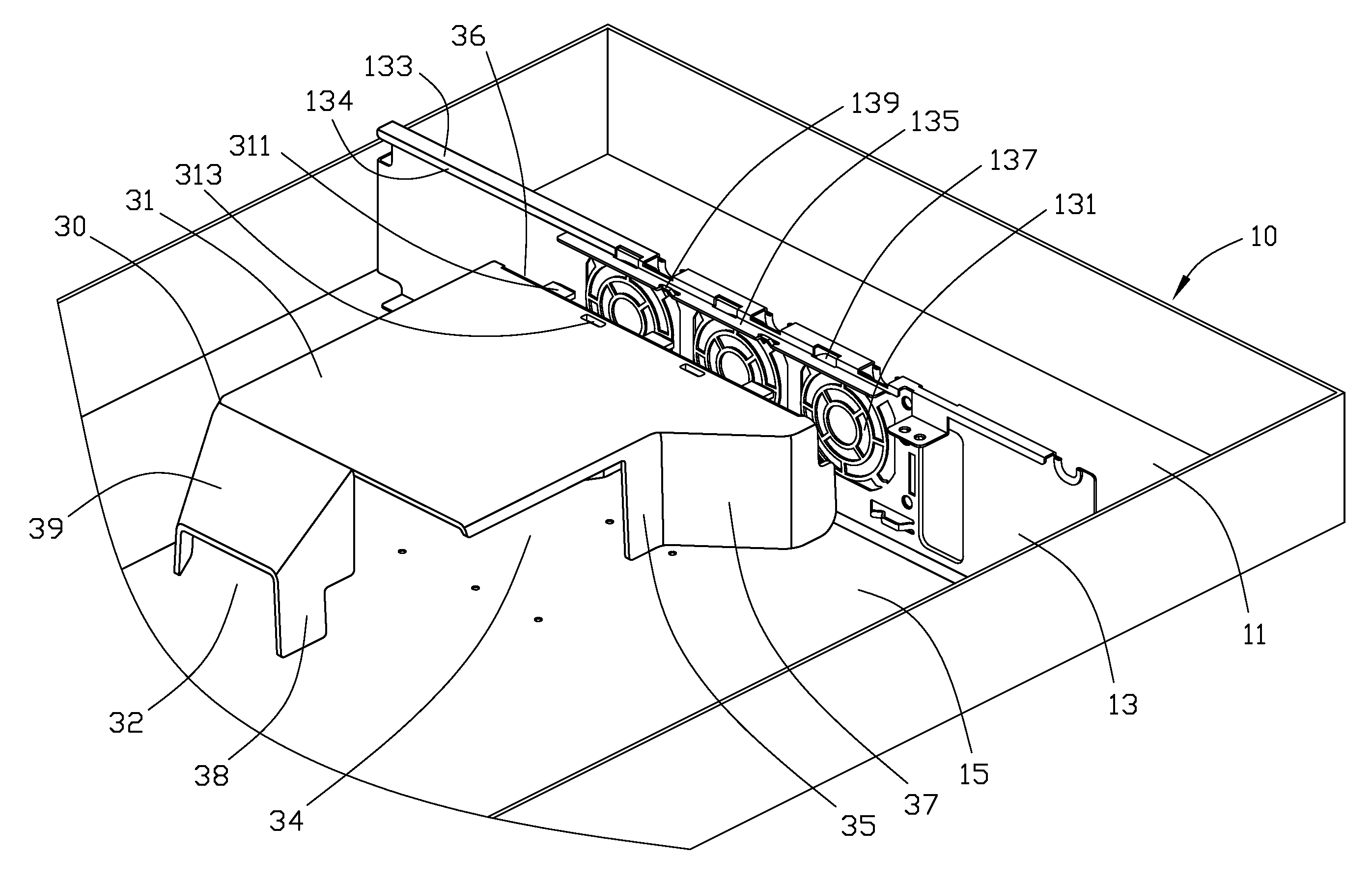
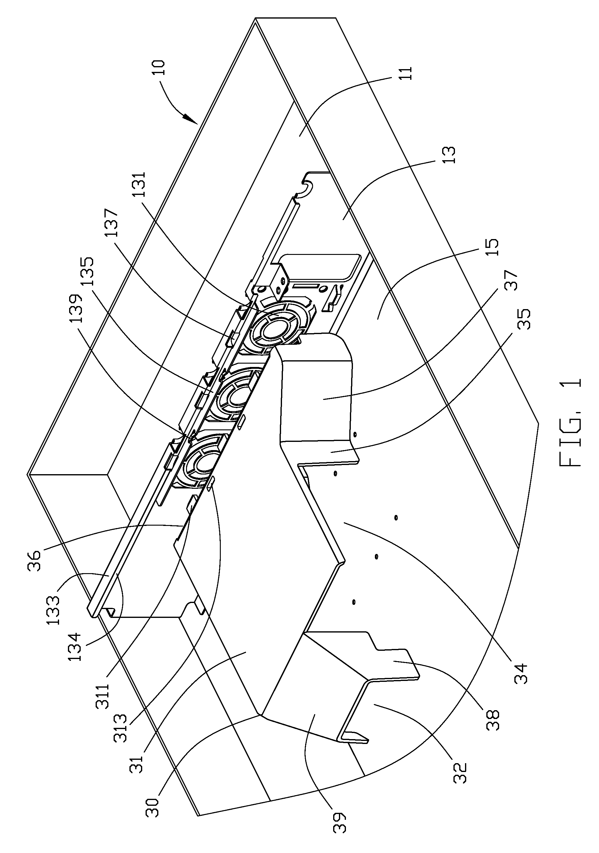
[0011]Referring to FIG. 1, a computer or server enclosure with an airflow guiding duct in accordance with the present invention includes a chassis 10, an airflow guiding duct 30, and a top cover 50 (shown in FIG. 3) mounted on the chassis 10.

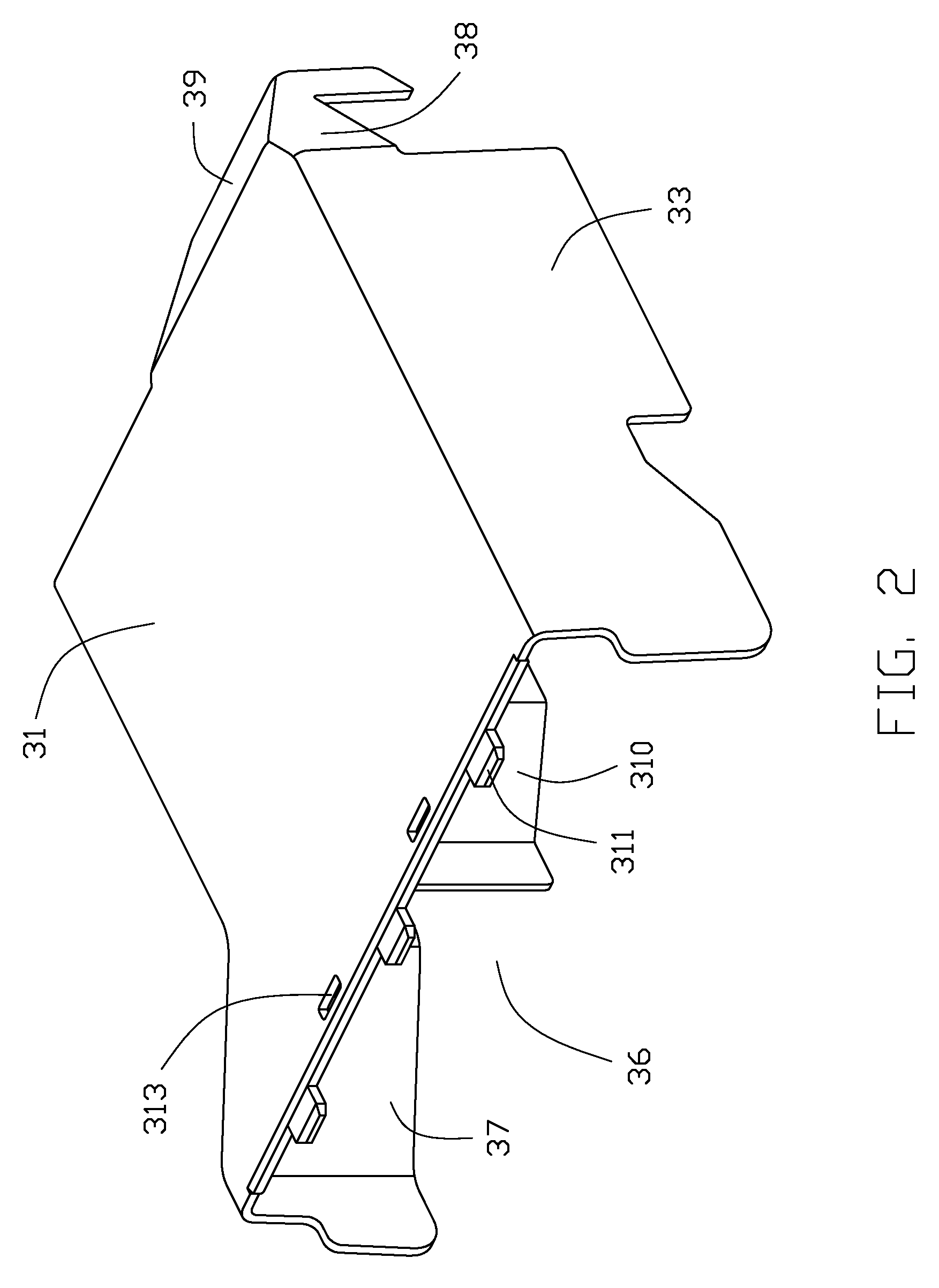
[0012]The chassis 10 includes a bottom wall 11 and a sidewall 13 perpendicular to the bottom wall 11. A motherboard 15 is mounted on the bottom wall 11 abutting the sidewall 13. A plurality of heat dissipating holes 131 is defined in the sidewall 13 for air flowing therethrough. A main flange 133 parallel to the motherboard 15 is perpendicularly bent from a top edge of the sidewall 13. A secondary flange 134 perpendicularly extends down from a side edge of the main flange 133. A supporting flange 135 parallel to the main flange 133 extends from a bottom edge of the secondary flange 134. A plurality of receiving slots 137 is spacedly defined in the secondary flange 134 at a joint of the main flange 133 and the supporting flange 135. A pair of sec...


PUM


Abstract

An electronic device with an airflow guiding duct includes a chassis, an airflow guiding duct, and a top cover. The chassis includes a bottom wall and a sidewall perpendicular to the bottom wall. A circuit board is mounted on the bottom wall. A pair of securing members protrudes from a top of the sidewall. The airflow guiding duct includes a top wall and a plurality of securing slots defined in the top wall corresponding to the securing members, for the securing members being lockingly engaging in the securing slots, thereby limiting movement of the airflow guiding duct in directions parallel to the circuit board. The cover is mounted on the chassis and abuts against the top wall of the airflow guiding duct, for limiting movement of the airflow guiding duct in a direction perpendicular to the circuit board.

Description

BACKGROUND[0001]1. Field of the Invention[0002]The present invention relates to electronic devices, particularly to an electronic device with an airflow guiding duct for heat dissipating modules therein.[0003]2. Description of Related Art[0004]A heat dissipating module is generally mounted on a motherboard of an electronic device, such as a computer or a server, for dissipating heat generated by electronic components in the electronic device. With the development of the computer industry, heat generated by the electronic components becomes greater due to faster speeds of the computers or servers. The conventional heat dissipating module cannot satisfy the requirements of current computer or server systems by itself so an airflow guiding duct is usually mounted above the heat dissipating module on the motherboard, for guiding airflow, increasing effectiveness heat dissipation. Conventionally, the airflow guiding duct is mounted in the electronic device via screws or bolts. This metho...

Claims


Application Information

Patent Timeline
Patent Type & Authority Patents(United States)
IPC IPC(8): H05K7/20
CPCH05K7/20727G06F1/20
Inventor WU, CHIA-KANGCHEN, LI-PING
Owner HON HAI PRECISION IND CO LTD
Why Eureka
Try Eureka