System and method for inspection of hole location on turbine airfoils

a technology of turbine airfoil and hole location, which is applied in the direction of electric/magnetic measuring arrangement, liquid fuel engine components, compasses, etc., can solve the problems of large floor space in production facilities, super-high temperatures of turbine blades downstream of combustion process, and high cost of systems

Inactive Publication Date: 2009-08-11
RTX CORP
View PDF25 Cites 31 Cited by
  • Summary
  • Abstract
  • Description
  • Claims
  • Application Information

AI Technical Summary

Problems solved by technology

Thus, blades of the turbine, which are downstream of the combustion process, are also subject to super-high temperatures.
Due to the CNC machine, such systems are quite expensive and take up a large amount of floor space in production facilities.
Also, for example, since as many as eighty holes must be individually inspected on each blade, inspection of a single blade may take as long as ten minutes.

Method used


Image

  • System and method for inspection of hole location on turbine airfoils
  • System and method for inspection of hole location on turbine airfoils
  • System and method for inspection of hole location on turbine airfoils

Examples


Embodiment Construction

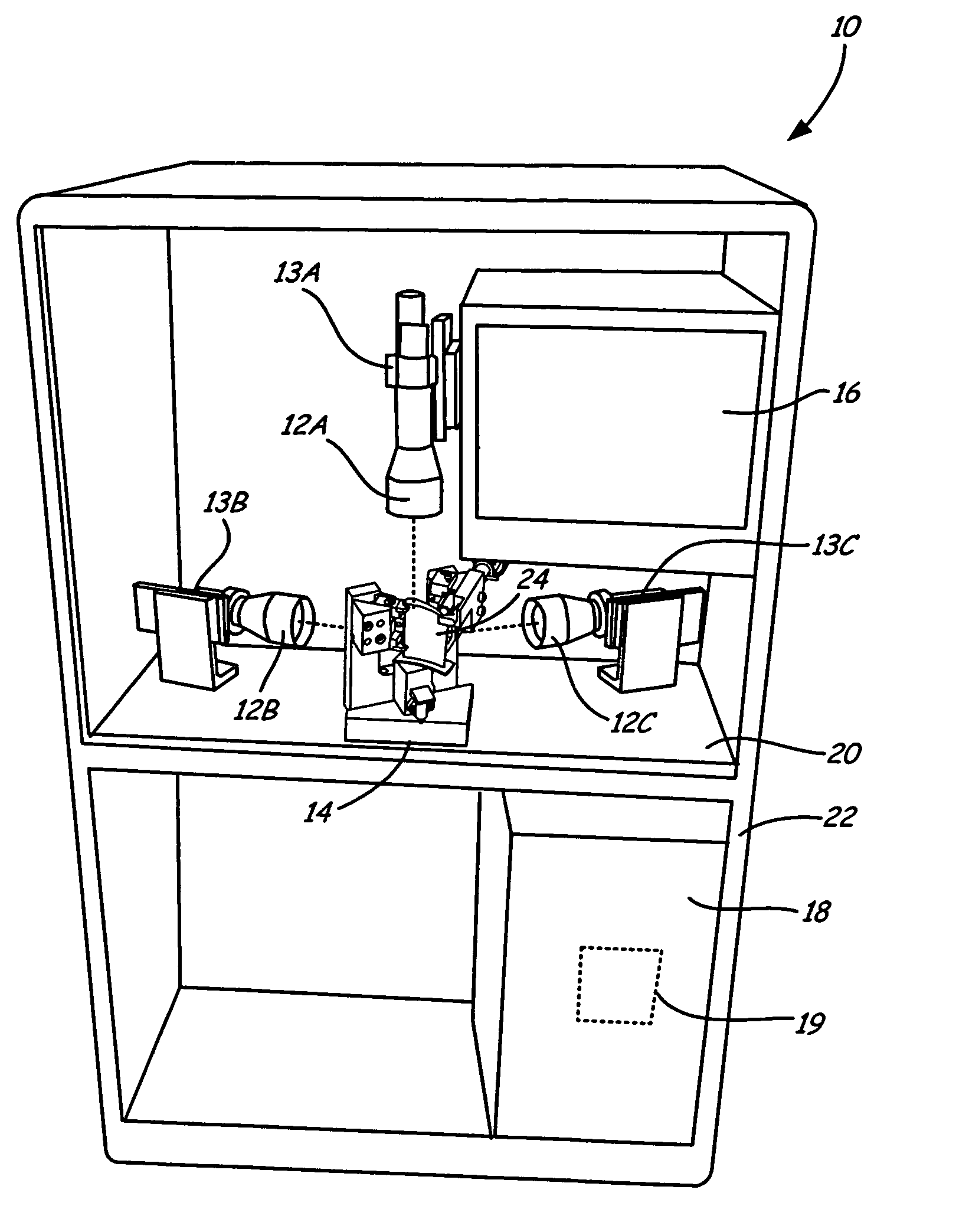
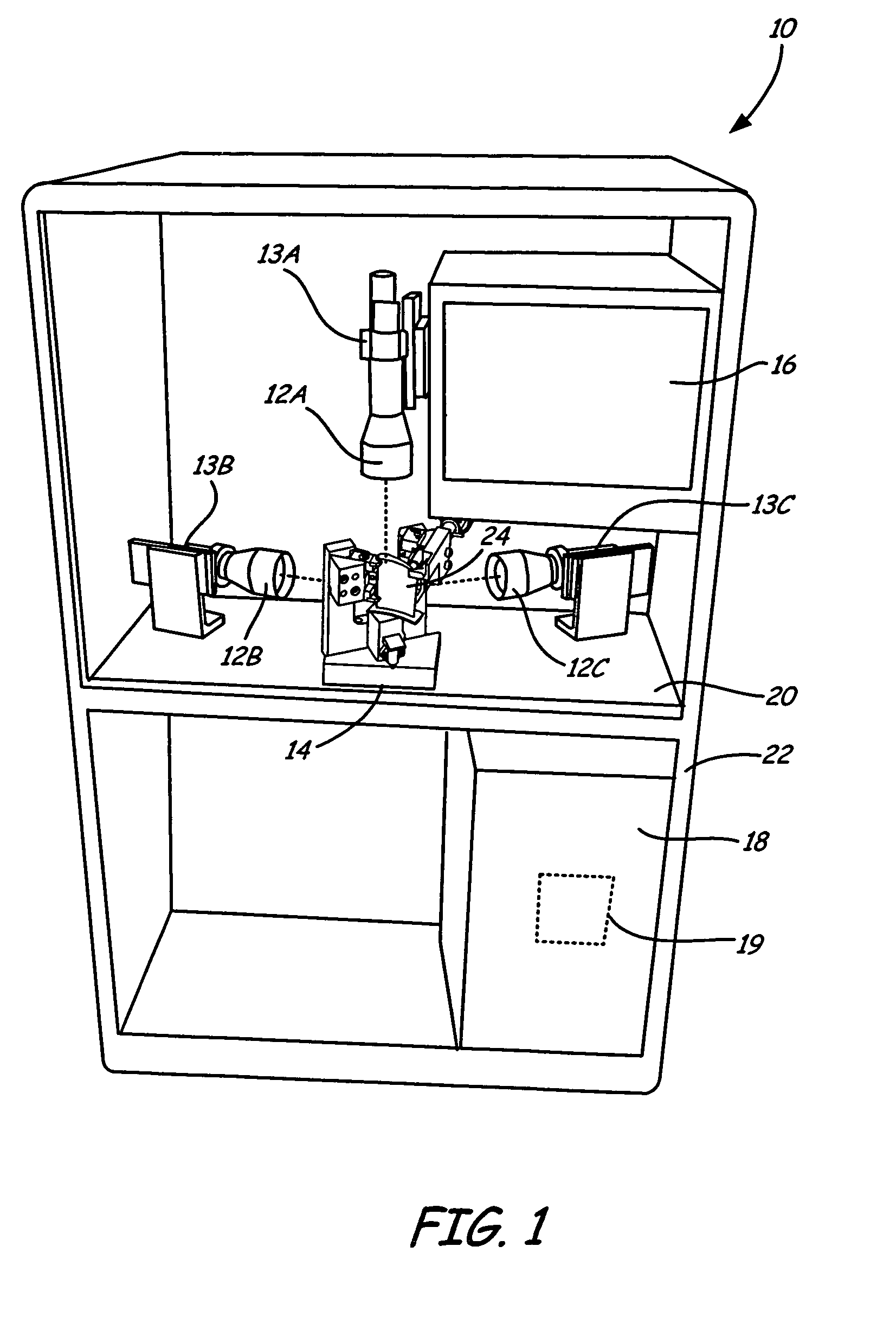
[0012]FIG. 1 shows a front view of inspection system 10 of the present invention. Inspection system 10 quickly and accurately locates the position of multiple features in a target object utilizing a video imaging system. Inspection system 10 comprises cameras 12A-12C, LED light sources 13A-13C, fixture 14, monitor 16, computer 18 and software 19. Cameras 12A-12C and fixture 14 are positioned on tabletop 20 within housing 22. Fixture 14 secures the target object, such as turbine blade 24, using a plurality of nest points in a specific orientation on tabletop 20 with respect to cameras 12A-12C. Monitor 16 and other user interface equipment are positioned in user friendly positions within housing 22, and are connected with computer 18, which is positioned under tabletop 20 within housing 22. Computer 18 includes software 19, including video-imaging and data processing software, used to locate the position of features, such as cooling holes, on turbine blade 24 with respect to reference...


PUM

PropertyMeasurementUnit
shapeaaaaaaaaaa
densityaaaaaaaaaa
temperaturesaaaaaaaaaa

Abstract

An inspection system for locating multiple features on an exterior of an object includes a fixture, a camera, a computer and software. The fixture secures the object and includes a plurality of nest points for mating with specific positions on the exterior of the object, and a reference point located at a specific position relative to the nest points and within a best-plane of the object. The camera is positioned normal to the best-plane of the object and obtains video imaging of a plurality of the features and the reference point. The computer communicates with the camera and collects the video imaging. The software determines the actual parameters of the features relative to the reference point based on the video imaging.

Description

BACKGROUND OF THE INVENTION[0001]This invention relates generally to systems and methods for inspecting manufactured articles and more particularly to systems and methods for locating hole features on a manufactured article.[0002]In gas turbine engines, fuel is combusted in compressed air in order to accelerate high-density air and to produce thrust, which, in turn, are used to turn a turbine shaft and drive an aircraft, respectively. During the combustion process, the air is heated to super-high temperatures in order to accelerate the air to produce the thrust. Thus, blades of the turbine, which are downstream of the combustion process, are also subject to super-high temperatures. In order to facilitate cooling of the blades, many turbine blades incorporate complex systems of internal cooling passages into which compressor bleed air, or another cooling fluid, is directed to cool the blade. The cooling air exits the blade through a system of holes arranged in such a manner that the ...

Claims


Application Information

Patent Timeline
Patent Type & Authority Patents(United States)
IPC IPC(8): G06K9/00F01D5/18G01B11/14H04N7/18G01B7/00
CPCF01D5/005G01B11/002G01B11/24F01D25/285B23P2700/06F05D2230/80
Inventor KOONANKEIL, JAMES M.
Owner RTX CORP
Why Eureka
Try Eureka