Circuit for dynamic circuit timing synthesis and monitoring of critical paths and environmental conditions of an integrated circuit

a dynamic circuit and environmental monitoring technology, applied in the field of integrated circuits, can solve the problems of decreasing the usable portion of the cycle-time, increasing the design difficulty of the integrated circuit, and increasing the complexity of the integrated circui

Inactive Publication Date: 2009-08-18
INT BUSINESS MASCH CORP
View PDF14 Cites 34 Cited by
  • Summary
  • Abstract
  • Description
  • Claims
  • Application Information

AI Technical Summary

Problems solved by technology

The design of integrated circuits has become increasingly difficult as a result of numerous challenges.
One particular challenge has been the ability to predict the cycle time (i.e. the time interval between the start of one cycle and the start of the next cycle) of large-scale integrated circuits.
In recent years, this has become progressively complicated from various factors (e.g., scaling) that increase the variation in process, across-chip line width, and response to environmental conditions.
Unfortunately with shrinking cycle-times and increasing process variations, the usable portion of the cycle-time has also been decreasing.
In other words, cycle time should not be dominated by the design margin, and therefore, cycle times must be increased which reduces the available performance of an integrated circuit in a given technology.
Unfortunately, this technique requires calibration of each integrated circuit at every desired operating point, and this unnecessarily consumes valuable test time.

Method used


Image

  • Circuit for dynamic circuit timing synthesis and monitoring of critical paths and environmental conditions of an integrated circuit
  • Circuit for dynamic circuit timing synthesis and monitoring of critical paths and environmental conditions of an integrated circuit
  • Circuit for dynamic circuit timing synthesis and monitoring of critical paths and environmental conditions of an integrated circuit

Examples


Embodiment Construction

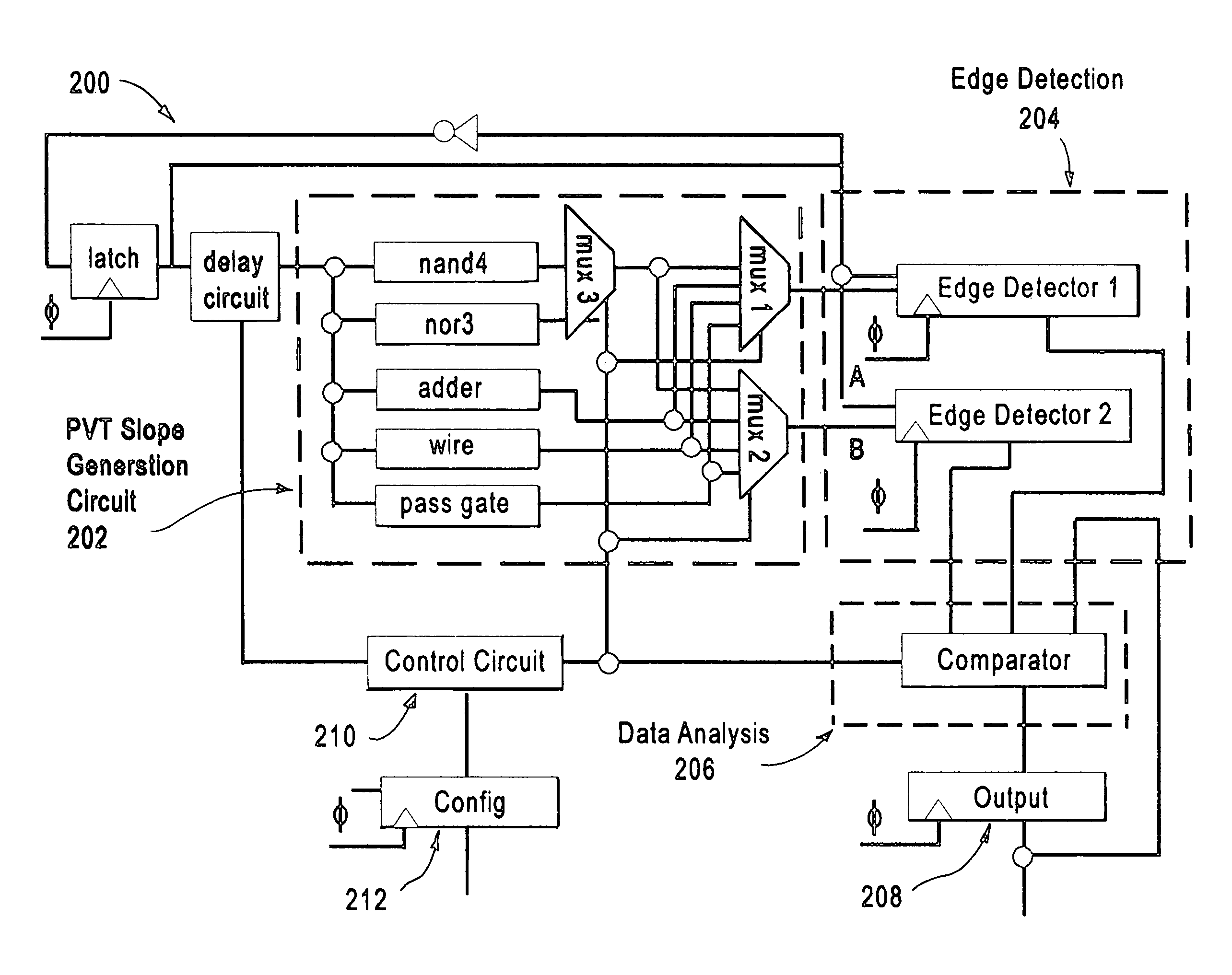
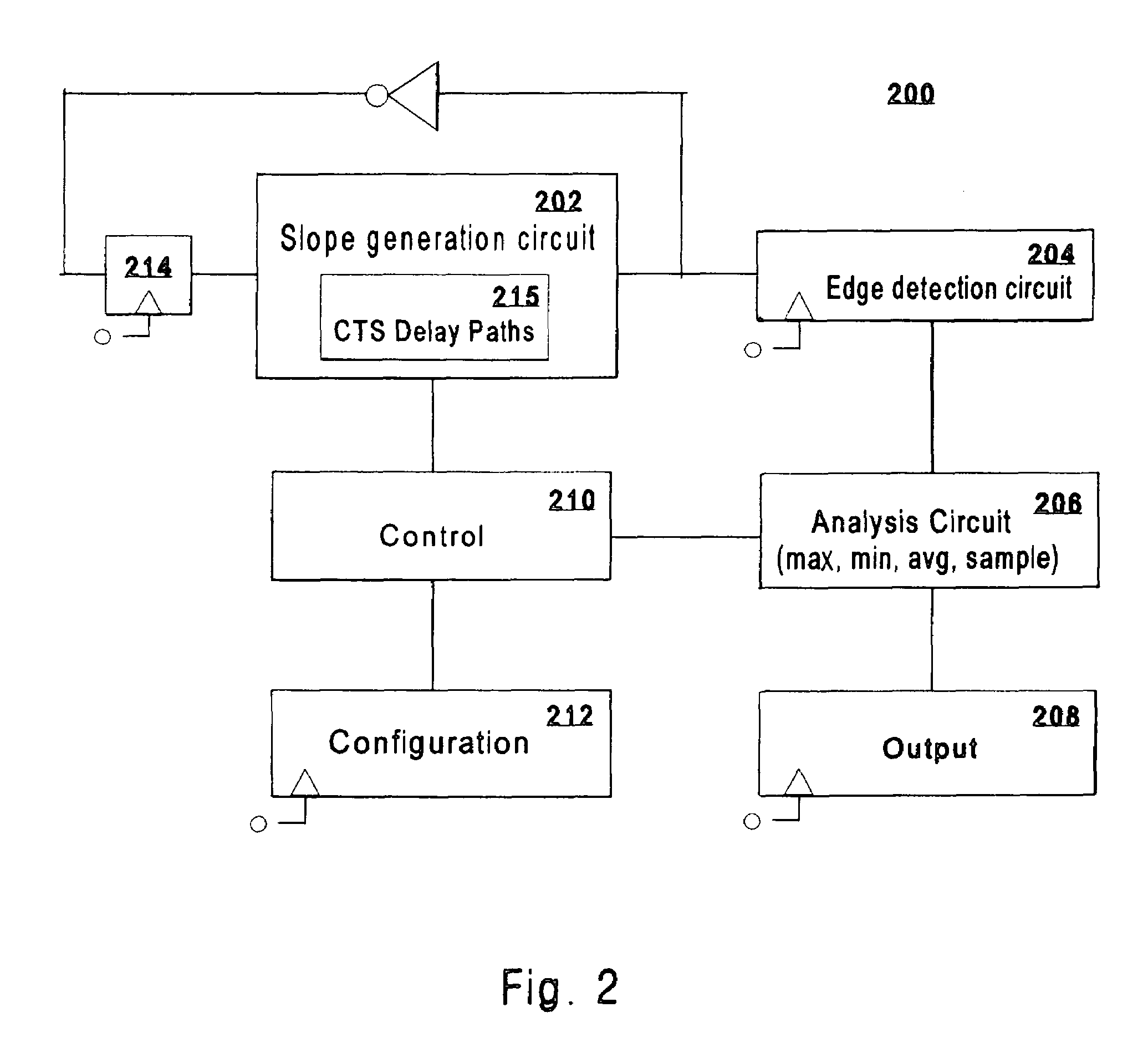
[0015]The present invention is a method and system for dynamically monitoring the timing associated with critical paths in an integrated circuit. In addition, the present invention also provides information concerning process and delay variations (e.g., Vdd droop, temperature, and process ageing).

[0016]The term “critical path” as used in this specification means a timing parameter within an integrated circuit including, but not limited to, the maximum propagation delay between latches in a circuit(s). For example, the delay of a sub-unit such as an adder can be monitored by the present invention, even though its timing may not necessarily limit the latch-to-latch timing of the entire integrated circuit. A path is considered critical when it is the first path to experience a timing failure as manufacturing process, voltage magnitude, or environmental effects degrade integrated circuit performance.

[0017]The term “interpolation” as used in this specification means combining two or more...


PUM


Abstract

A circuit for dynamically monitoring the operation of an integrated circuit under differing temperature, frequency, and voltage (including localized noise and droop), and for detecting early life wear-out mechanisms (e.g., NBTI, hot electrons).

Description

[0001]This invention was made with government support under DARPA, NBCH3039004. THE GOVERNMENT HAS CERTAIN RIGHTS IN THIS INVENTIONBACKGROUND[0002]1. Technical Field of the Present Invention[0003]The present invention generally relates to integrated circuits and, more specifically, to circuits that perform dynamic circuit timing synthesis and monitor critical paths and environmental conditions of the integrated circuit.[0004]2. Description of Related Art[0005]The design of integrated circuits has become increasingly difficult as a result of numerous challenges. One particular challenge has been the ability to predict the cycle time (i.e. the time interval between the start of one cycle and the start of the next cycle) of large-scale integrated circuits. In recent years, this has become progressively complicated from various factors (e.g., scaling) that increase the variation in process, across-chip line width, and response to environmental conditions.[0006]The most common solution f...

Claims


Application Information

Patent Timeline
Patent Type & Authority Patents(United States)
IPC IPC(8): G01R29/02G06F17/50H03K5/22
CPCG06F17/5036G06F17/5031G06F30/3312G06F30/367
Inventor CARPENTER, GARY D.DRAKE, ALAN J.DEOGUN, HARMANDER S.FLOYD, MICHAEL S.JAMES, NORMAN K.SENGER, ROBERT M.
Owner INT BUSINESS MASCH CORP
Why Eureka
Try Eureka