Method and apparatus for fault localization in a network

a fault localization and network technology, applied in the field of communication networks, can solve problems such as failure to report, information available, and wide and volatile set of failure modes in networks

Inactive Publication Date: 2009-08-18
AMERICAN TELEPHONE & TELEGRAPH CO
View PDF2 Cites 25 Cited by
  • Summary
  • Abstract
  • Description
  • Claims
  • Application Information

AI Technical Summary

Problems solved by technology

Such networks suffer from a wide and volatile set of failure modes.
While there are automated mechanisms for locating faults with a layer (e.g., SONET), such mechanisms may fail to report faults giving rise to “silent faults,” or there may not be information available from these mechanisms for diagno

Method used


Image

  • Method and apparatus for fault localization in a network
  • Method and apparatus for fault localization in a network
  • Method and apparatus for fault localization in a network

Examples


Embodiment Construction

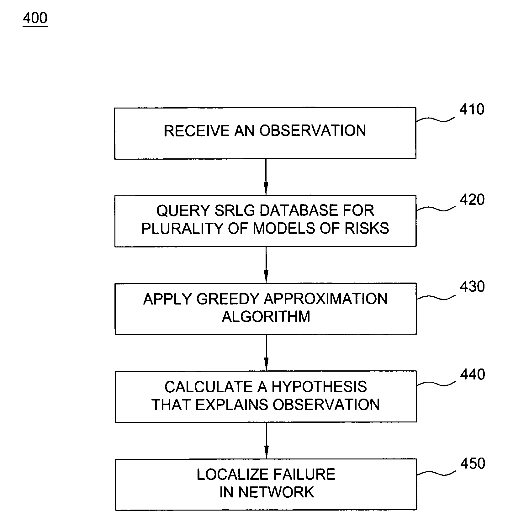
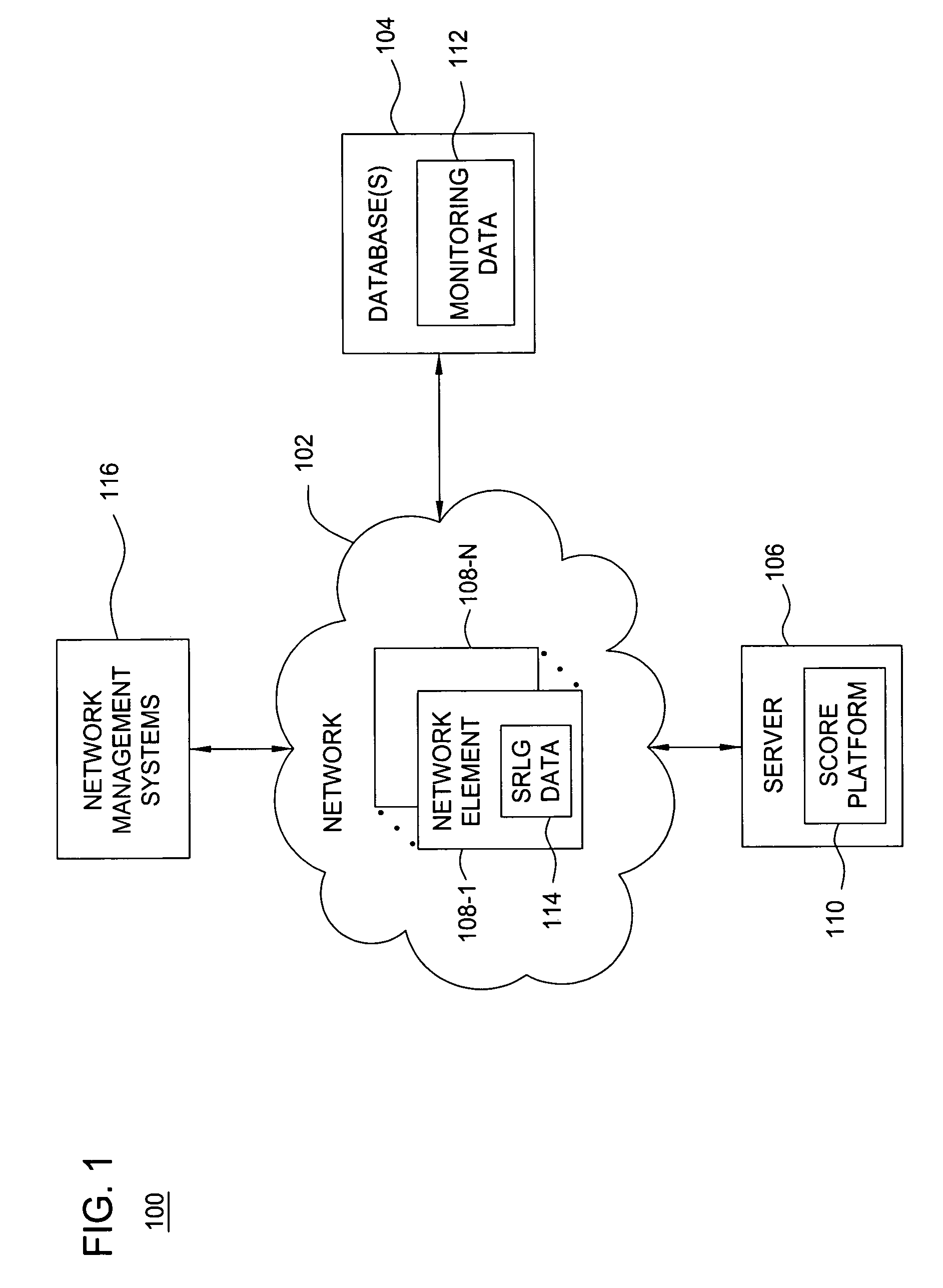
[0012]FIG. 1 is a block diagram depicting an exemplary network architecture 100 in accordance with one or more aspects of the invention. The network architecture 100 includes a network 102, one or more databases 104, and a server 106. The network 102 includes network elements 108-1 through 108-N (collectively referred to as network elements 108). The network 102 includes a packet network portion and a core transport network portion. The core transport network portion is typically an optical network. The network elements 108 comprise various types of network devices employed in packet networks and optical transport networks, such as routers, optical amplifiers, wavelength division multiplexing (WDM) systems, switches, cross-connects, and like type network devices known in the art. Network layer links (e.g., Internet Protocol (IP) links) are used to communicate data packets among the network elements 108.

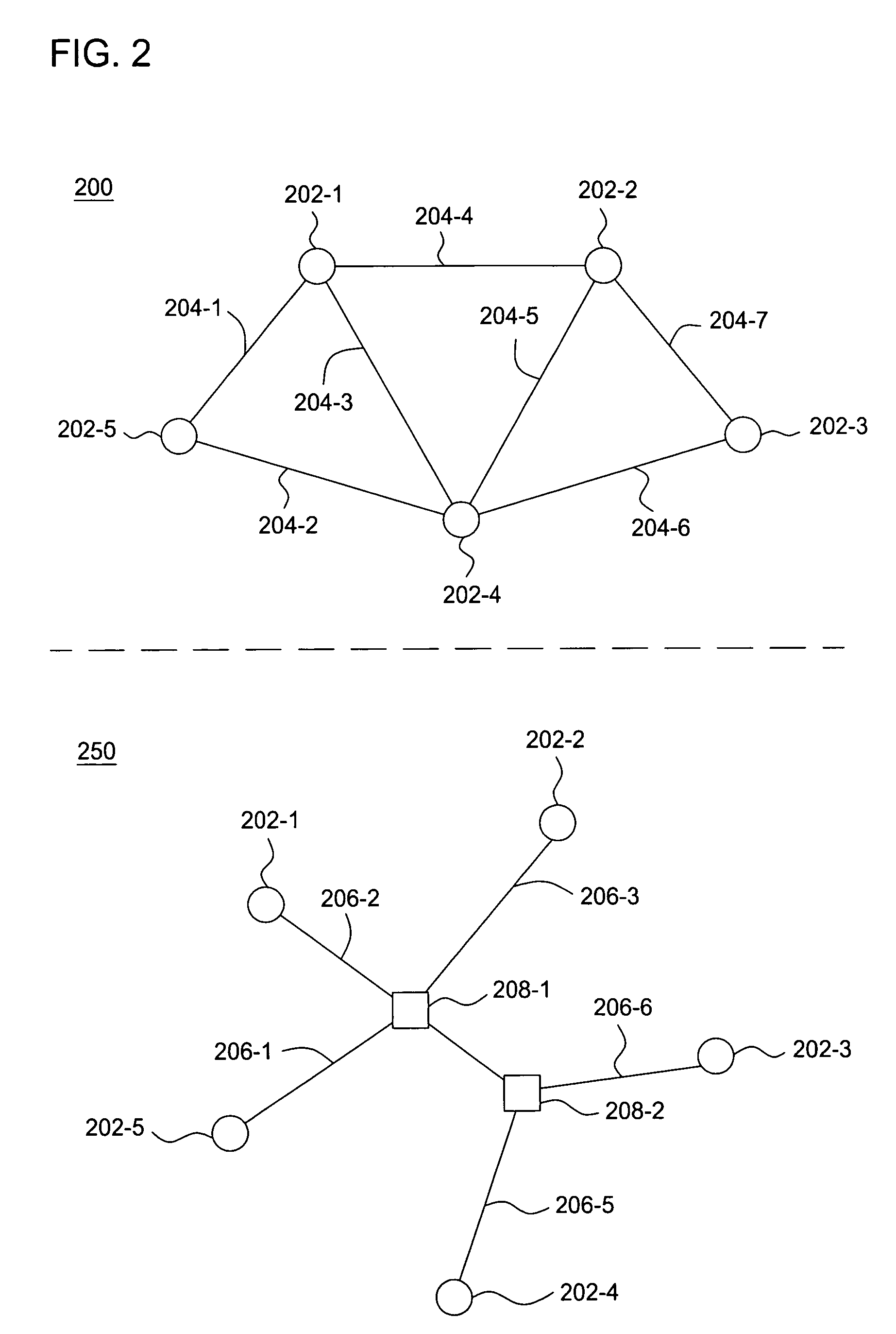
[0013]FIG. 2 is a block diagram depicting an exemplary network topology in accord...


PUM


Abstract

A method and apparatus for automatically localizing failures in a network. Failures can be localized by receiving an observation, querying a database for a plurality of models of risks and calculating a hypothesis from the plurality of models of risks that explains the observation. The observation comprises link failures reported by a plurality of data sources. The plurality of models or risks represents links that would likely be impacted by the failure of each component within the network stored in a Shared Risk Link Group (SRLG) database. A Spatial Correlation Engine (SCORE) applies an algorithm to calculate a hypothesis from the plurality of models of risks that explains the observation, thereby, automatically localizing failures in a network.

Description

BACKGROUND OF THE INVENTION[0001]1. Field of the Invention[0002]The present invention relates generally to communication networks and, more particularly, to a method and apparatus for fault localization in a network, e.g. internet protocol (IP) and optical networks.[0003]2. Description of the Related Art[0004]Today's networks are large, geographically distributed and constantly evolving. Such networks suffer from a wide and volatile set of failure modes. Conventionally, network fault management is performed manually by correlating a large number of failure notifications and alarms to determine which network elements have failed. While there are automated mechanisms for locating faults with a layer (e.g., SONET), such mechanisms may fail to report faults giving rise to “silent faults,” or there may not be information available from these mechanisms for diagnosing reported faults. When an underlying failure in a network proves difficult to detect and localize, the duration of degraded...

Claims


Application Information

Patent Timeline
IPC IPC(8): G01R31/08G06F11/00G08C15/00H04J1/16H04J3/14H04L1/00H04L12/16
CPCH04Q3/0075H04L41/0677H04L41/0213
Inventor GREENBERG, ALBERT G.KOMPELLA, RAMANA RAOSNOEREN, ALEX C.YATES, JENNIFER
Owner AMERICAN TELEPHONE & TELEGRAPH CO
Why Eureka
Try Eureka